890370_0•en•01.06.2009
We reserve the right to carry out improvements
44
WAREMA climatronic
®
Installation Instructions
Connection information
123456789
97643
Switching actuator
6M
X8
X4
E
6.2
E
6.1
P
E
5.2
P
E
5.1
E
4.2
E
4.1
ANW
123456789
X9
PP
V1 V2 V3 V4 V5 V6
GLT
A
5.1
A
5.2
F3
6,3 AT
C
5/6
A
6.1
A
6.2
Stör
2
N
L
PE
Green(OK)
Red (fault)
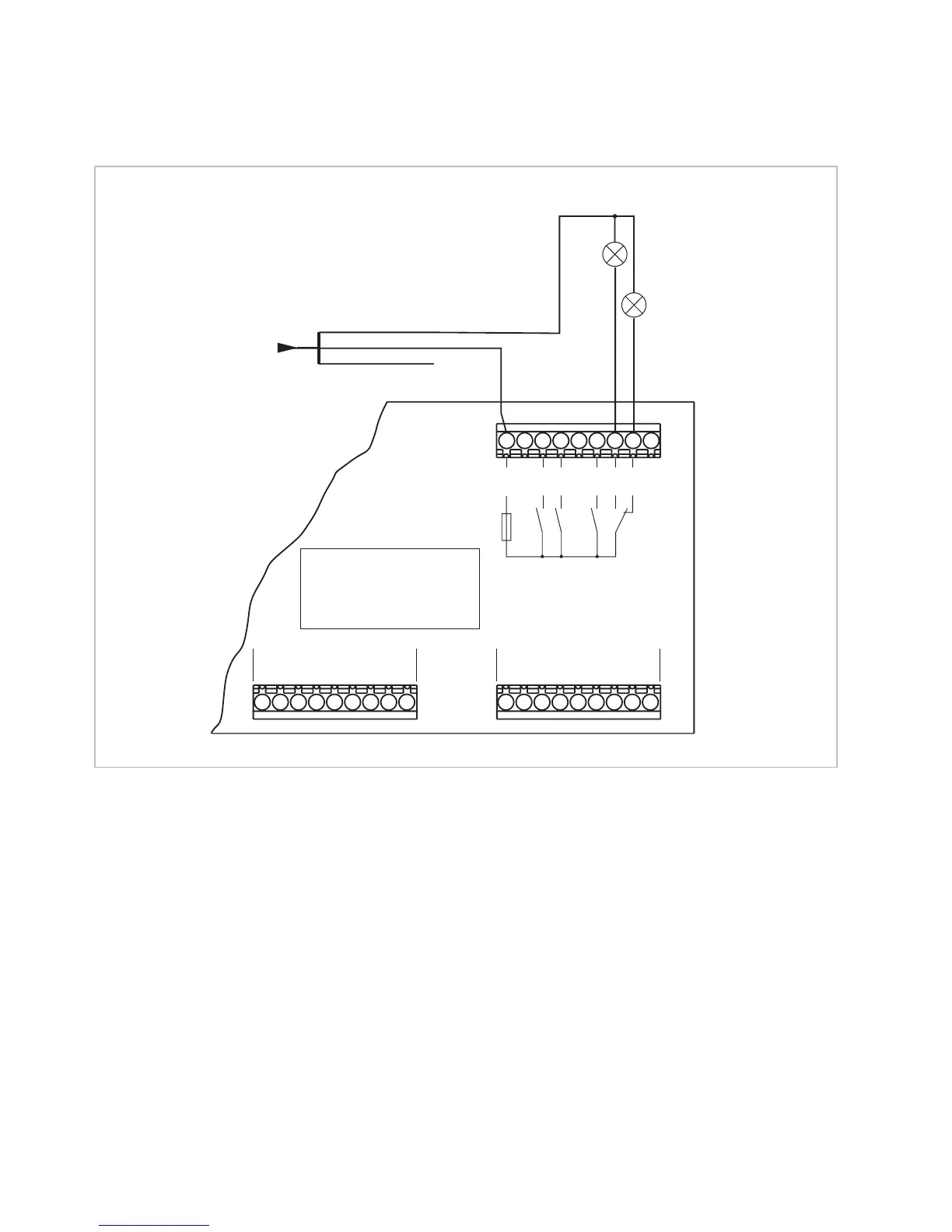
Fig. 23 Connection example of fault sensor contact
When de-energised (idle state) and if there is a fault, the "Fault" contact is
closed. When there is no fault, the relay pulls in and contact A 6.2 closes.
The fault sensor contact can only be connected to the 6M or 6M230 actuator
(A 6.2/fault).
During commissioning, one channel must be reserved for the product fault
sensor contact.
The fault sensor contact is activated when:
Bus communication fails
An actuator fails
A control panel, weather station or humidity/temperature sensor fails
The E 6.2 input does not have a function in this circuit and must not be used.
NOTE The 4M and 4M230 switch actuators do not have a fault sensor contact.