Procedure:
1. Lead the temperature sensor (Figure 21) through the cable entry grommet
(Section +C1) (Figure 103).
NOTICE: The sensor must protrude completely out of the product (Figure 104).
2. Ensure that Enable switch is in position OFF.
3. Ensure that the DC switches and AC switches are in position 0.
4. Perform all checks described in Section 4.6.4 (Sections +C2, +C5).
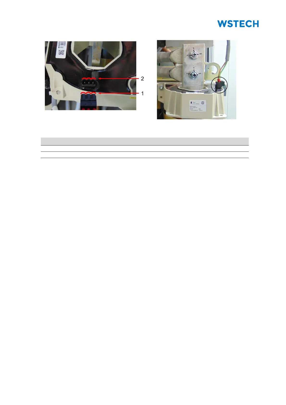
5. Check that all current transformer cables have the proper distance to the
inductor connection (Sections +C3, +C6) (Figure 106).
NOTICE: There are 3 current transformers per inductor.
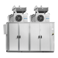
6. Check that all plugs of the current transformers are properly connected
(Sections +C3, +C6).
NOTICE: Observe the profile of the plug and connector before connecting with the
current transformer (Figure 107, Figure 108).
7. Check that all door switches are repositioned (Section 4.3.2).
8. Check that all connection cables and supply lines are connected correctly.
9. Check input voltages, rotary field and polarity.
10. Install LV-fuses into LV-fuse holder (Sections +C2, +C5).
11. Switch the miniature circuit breaker (-F1) and (-FC3) in position I
(Section +C1).
12. Ensure that all protective covers are mounted.
13. Close all doors.
14. Switch the Enable switch in position ON.
15. If necessary, perform initial setup via the user interface.