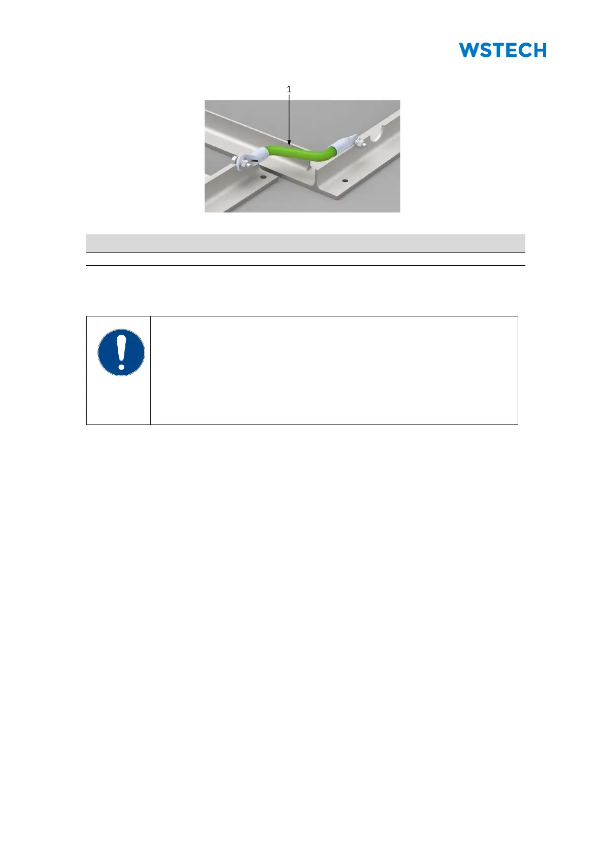
NOTICE
Dimensioning of the AC cables!
The ampacity of the AC terminals depends on the APU current.
• The maximum output current of the APS evenly distributed on
the AC terminals according to the number of the APUs (Table 15
to Table 18).
Requirement:
• All grid parameters must be fulfilled (Section 12.2).
Requirements for IT systems:
• No other loads may be connected.
• The maximum capacity against earth must be maximum 2000 µF for each
IT system.
Information for cable dimensioning:
• The APU current is shown in Section 12.2.
• The ambient temperature in the connection area is < 70°C.
• The AC connection of the phases from the transformer is illustrate in Table 19
and Figure 82 to Figure 84.
• To define the AC cable lengths, look at Figure 85 and Figure 86.