Required material:
• 30 litres of cooling fluid (50 % glycol / 50 % distilled water) for each cooling
system
• Funnel with filter
NOTICE: The cooling system is not completely filled with cooling fluid. After connecting
the cooling tower, the customer must completely fill the cooling system up to the fluid
level.
Procedure:
1. First establish the electrical connection (Section 4.6).
2. Ensure that ball valves are in position OFF.
3. Use the funnel with filter (separate packaging) to fill in the cooling fluid.
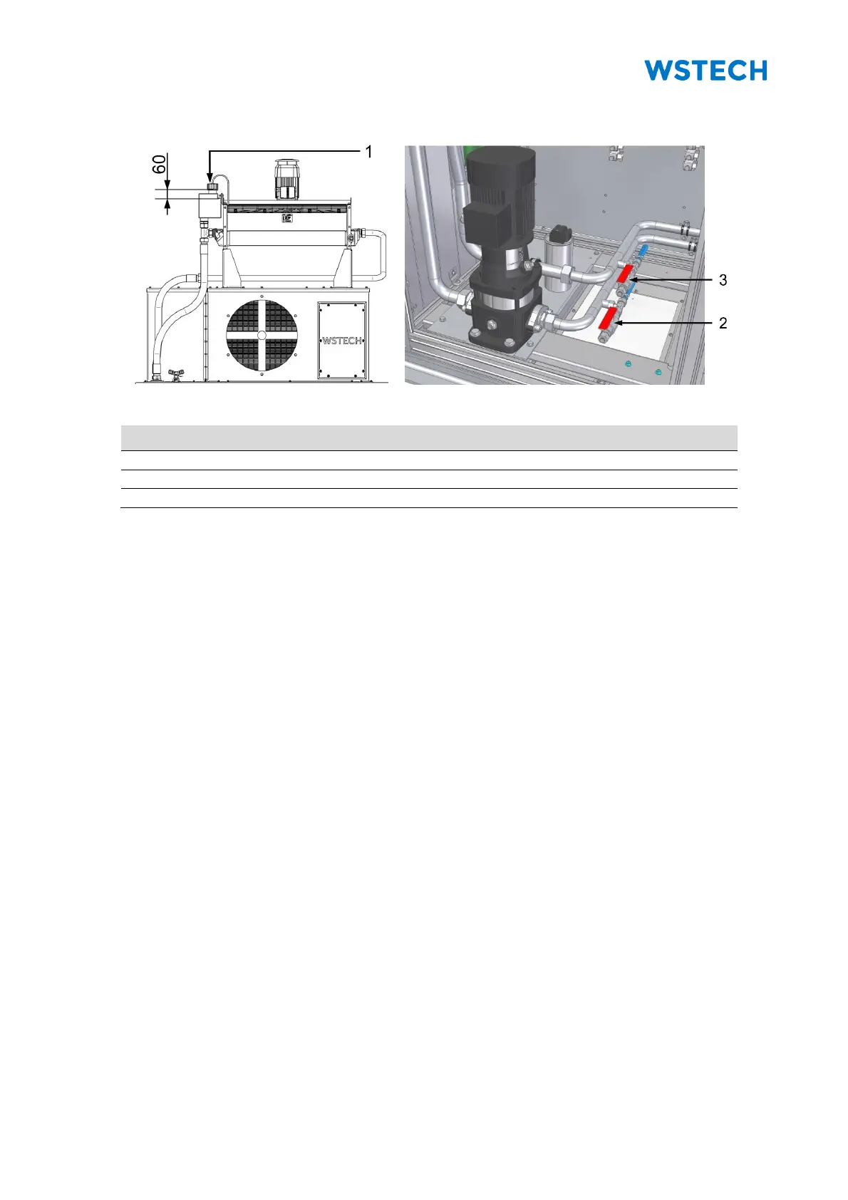
4. Completely fill cooling system with cooling fluid via the tank at the top
(Figure 74).
5. Switch on the supply voltage (-F1) and control voltage (-FC3) inside control unit
(Figure 21).
6. Shortly operate water pumps via the user interface (Function and Interface
Description).
7. Refill cooling fluid until the cooling system is completely vented.
NOTICE: It is completely vented, when the cooling fluid is 60 mm below from the top of
the tank nozzle (Figure 74).
8. Check fluid level with a measuring equipment and a lamp.