2. Dismount the service access cover (Figure 61, A).
3. Dismount the service access cover (Figure 62, B).
NOTICE: Observe the instructions for processing the assembly paste.
4. Apply the assembly paste on all threaded studs.
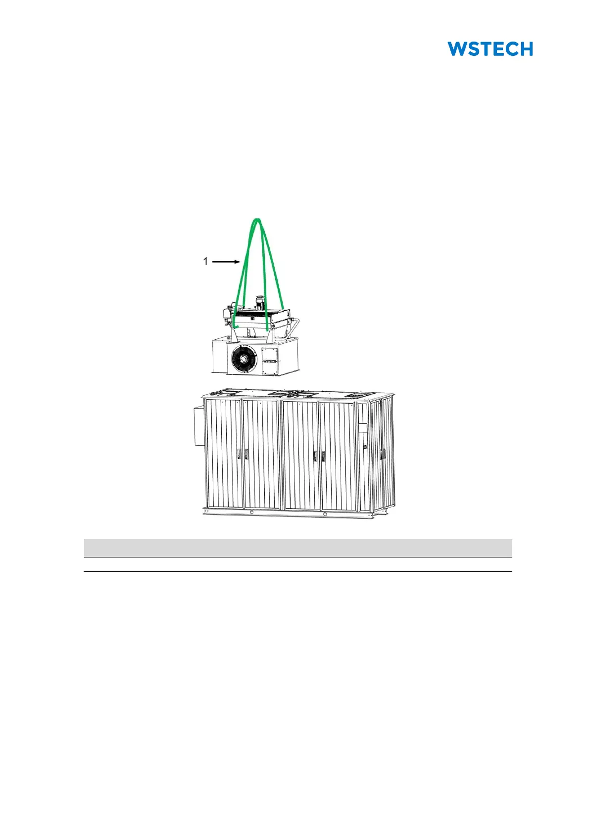
5. Carefully position the cooling tower (Figure 64).
NOTICE: The cooling tower is correctly positioned, if all screw connections (Figure 63,
C) can be screwed with the top cover.
Figure 64: Positioning of cooling tower