10-12 Phaser 3250 Laser Printer Service Manual
Plug/Jack and Wiring Diagrams
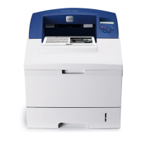
Denotes a Photo Sensor.
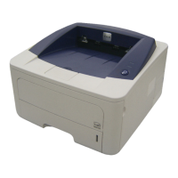
Denotes a Safety Interlock Switch.
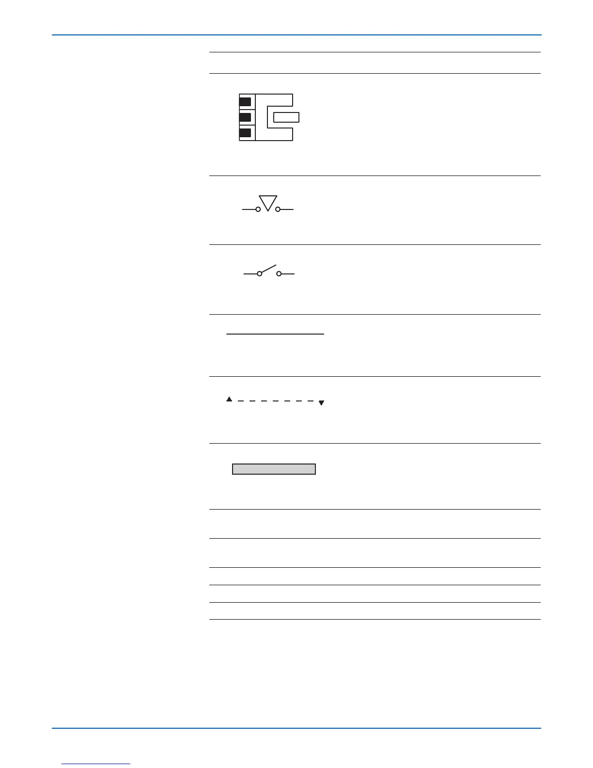
Denotes an On-Off Switch (single-pole, single-
throw switch).
Represents an interconnection between parts
using wiring harness or wire.
Represents an interconnection which differs
according to the specifications.
Represents an interconnection between parts
using a conductive part such as a Plate Spring.
I/L +24 VDC Denotes DC voltage when the Interlock Switch in
the MCU Board turns On.
+5 VDC
+3.3 VDC
Denotes DC voltage.
SG Denotes signal ground.
AG Denotes analog ground.
RTN Denotes return.
Symbol
Description
Interconnection, Differing
Interconnection, Conductive Part