BALANCERS
5-110
2. Align:
• “T” mark on the pickup rotor
(with the crankcase mating surface)
▼▼▼▼ ▼ ▼▼▼▼▼▼▼▼▼ ▼ ▼▼▼▼ ▼ ▼▼▼▼ ▼ ▼▼▼▼▼▼▼
a. Turn the crankshaft clockwise.
b. When piston #1 is at TDC on the compres-
sion stroke, align the “T” mark “a” on the pick-
up rotor with the crankcase mating surface
“b”.
TDC on the compression stroke can be found
when the camshaft lobes are turned away from
each other.
▲▲▲▲ ▲ ▲▲▲▲▲▲▲▲▲ ▲ ▲▲▲▲ ▲ ▲▲▲▲ ▲ ▲▲▲▲▲▲▲
3. Install:
• Rear balancer shaft
▼▼▼▼ ▼ ▼▼▼▼▼▼▼▼▼ ▼ ▼▼▼▼ ▼ ▼▼▼▼ ▼ ▼▼▼▼▼▼▼
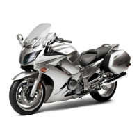
a. Align the punch marks “a” in the balancer
weight with the punch mark “b” in the upper
crankcase.
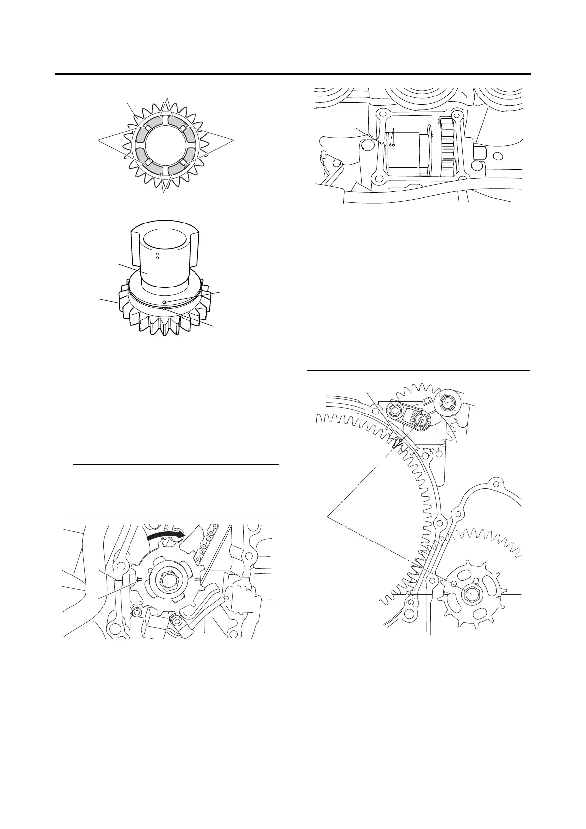
b. Align the balancer gear punch mark “c” with
the primary driven gear point “d” as shown.
• Make sure that the rear balancer gear teeth
and the primary driven gear teeth mesh cor-
rectly.
• Make sure that the balancer gear punch mark
“c” is aligned with the projection “e” on the up-
per crankcase.
• Make sure that the slot “f” is facing in the direc-
tion indicated in the illustration when installing
the balancer shaft.
17
16
15
14
13
12
11
10
9
8
7
6
5
4
3
2
1
c
d