AIR INDUCTION SYSTEM
7-16
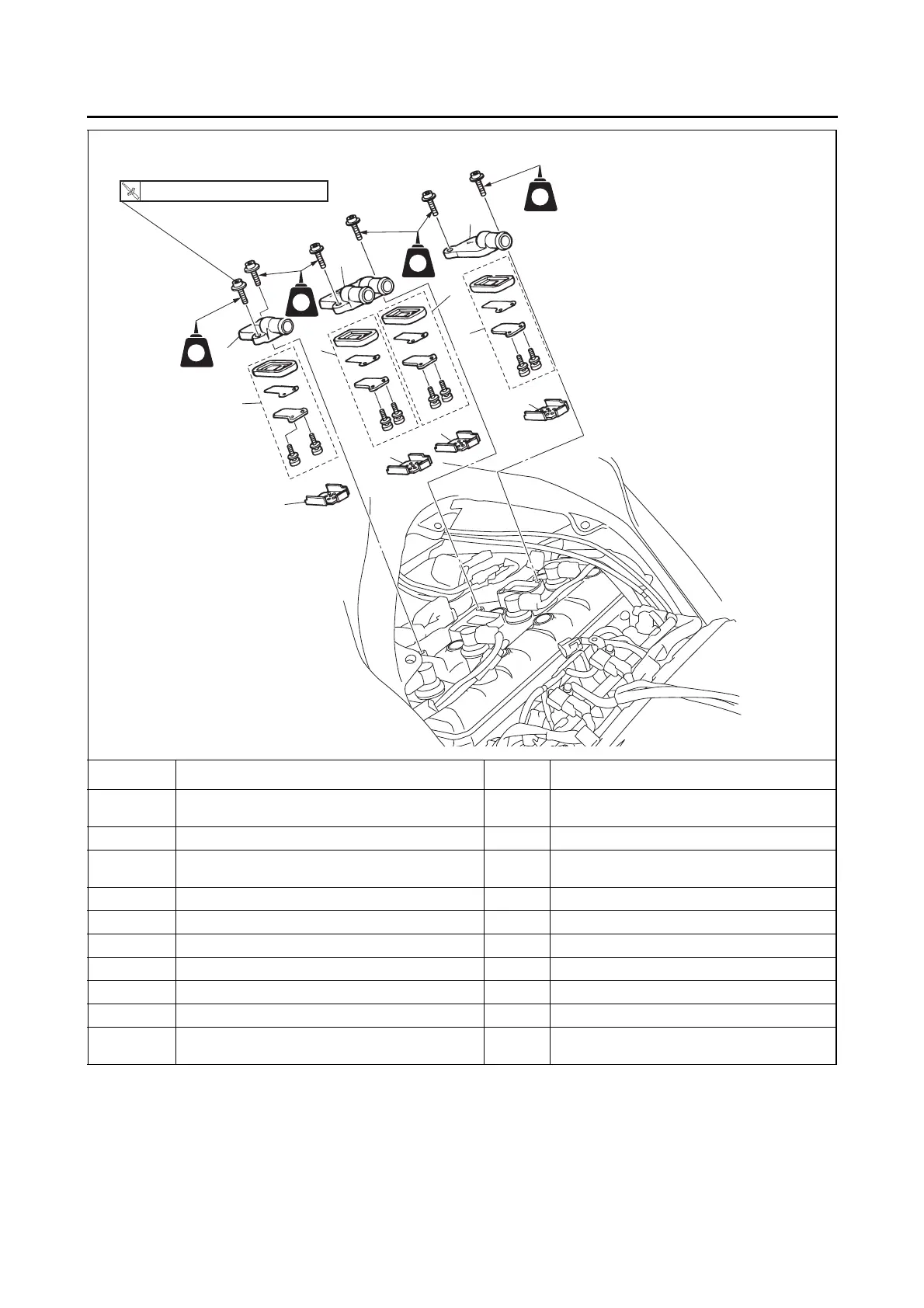
Removing the reed valves
Order Job/Parts to remove Q’ty Remarks
Rider seat/T-bar
Refer to “GENERAL CHASSIS” on page
4-1.
Fuel tank Refer to “FUEL TANK” on page 7-1.
Air induction system hoses (3-way joint to reed
valve cover)
Refer to “Removing the air cut-off valve”.
Thermostat inlet pipe 1 Refer to “THERMOSTAT” on page 6-6.
1 Reed valve cover (cylinder-#1) 1
2 Reed valve cover (cylinders-#2/#3) 1
3 Reed valve cover (cylinder-#4) 1
4 Reed valve assembly 4
5 Reed valve plate 4
For installation, reverse the removal proce-
dure.
LT
LT
LT
LT
1
4
5
2
3
4
4
4
5
5
5
14 Nm (1.4 m
•
kg, 10 ft
•
Ib)
T
.R.