ELECTRICAL COMPONENTS
8-181
▼▼▼▼ ▼ ▼▼▼▼▼▼▼▼▼ ▼ ▼▼▼▼ ▼ ▼▼▼▼ ▼ ▼▼▼▼▼▼▼
a. Disconnect the relay unit coupler from the
wire harness.
b. Connect the pocket tester (Ω × 1) to the relay
unit terminal as shown.
c. Check the relay unit (diode) for continuity.
d. Check the relay unit (diode) for no continuity.
▲▲▲▲ ▲ ▲▲▲▲▲▲▲▲▲ ▲ ▲▲▲▲ ▲ ▲▲▲▲ ▲ ▲▲▲▲ ▲▲▲
EAS28100
CHECKING THE IGNITION COILS
The following procedure applies to all of the igni-
tion coils.
1. Check:
• Primary coil resistance
Out of specification → Replace.
▼▼▼▼ ▼ ▼▼▼▼▼▼▼▼▼ ▼ ▼▼▼▼ ▼ ▼▼▼▼ ▼ ▼▼▼▼ ▼▼▼
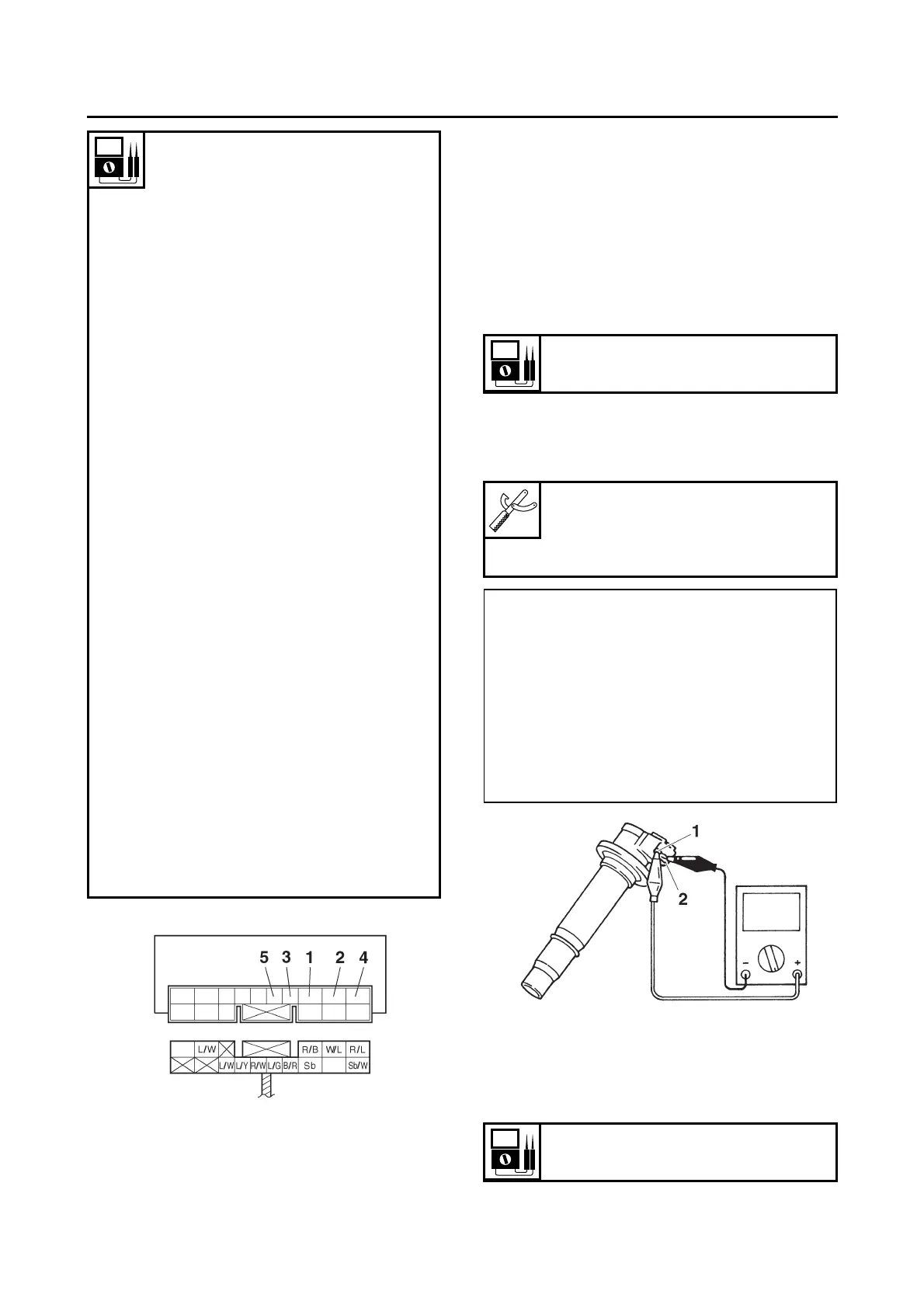
a. Remove the ignition coil from the spark plug.
b. Connect the pocket tester (Ω × 1) to the igni-
tion coil as shown.
c. Measure the primary coil resistance.
▲▲▲▲ ▲ ▲▲▲▲▲▲▲▲▲ ▲ ▲▲▲▲ ▲ ▲▲▲▲ ▲ ▲▲▲▲ ▲▲▲
2. Check:
• Secondary coil resistance
Out of specification → Replace.
Continuity
Positive tester probe → sky blue
“1”
Negative tester probe →
black/yellow “2”
No continuity
Positive tester probe →
black/yellow “2”
Negative tester probe → sky
blue “1”
Continuity
Positive tester probe → sky blue
“1”
Negative tester probe →
black/red “3”
No continuity
Positive tester probe →
black/red “3”
Negative tester probe → sky
blue “1”
Continuity
Positive tester probe → sky blue
“1”
Negative tester probe → sky
blue/white “4”
No continuity
Positive tester probe → sky
blue/white “4”
Negative tester probe → sky
blue “1”
Continuity
Positive tester probe →
blue/green “5”
Negative tester probe →
black/red “3”
No continuity
Positive tester probe →
black/red “3”
Negative tester probe →
blue/green “5”
Primary coil resistance
1.19–1.61 Ω
Pocket tester
90890-03112
Analog pocket tester
YU-03112-C
• Positive tester probe →
red/black “1”
• Negative tester probe →
Cylinder-#1 ignition coil
orange “2”
Cylinder-#2 ignition coil
gray/red “2”
Cylinder-#3 ignition coil
orange/green “2”
Cylinder-#4 ignition coil
gray “2”
Secondary coil resistance
8.50–11.50 kΩ