ELECTRICAL COMPONENTS
8-183
b. Measure the crankshaft position sensor re-
sistance.
▲▲▲▲ ▲ ▲▲▲▲▲▲▲▲▲ ▲ ▲▲▲▲ ▲ ▲▲▲▲ ▲ ▲▲▲▲▲▲▲
EAS28130
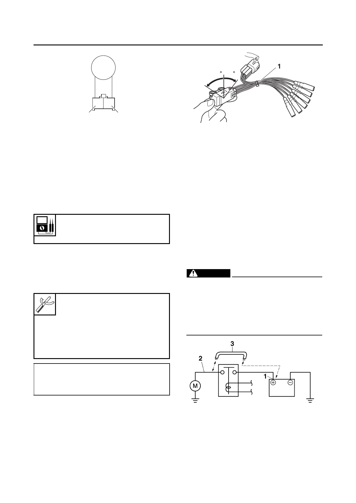
CHECKING THE LEAN ANGLE SENSOR
1. Remove:
• Lean angle sensor
(from the rear fender)
2. Check:
• Lean angle sensor output voltage
Out of specification → Replace.
▼▼▼▼ ▼ ▼▼▼▼▼▼▼▼▼ ▼ ▼▼▼▼ ▼ ▼▼▼▼ ▼ ▼▼▼▼▼▼▼
a. Connect the test harness-lean angle sensor
(6P) “1” to the lean angle sensor and wire
harness as shown.
b. Connect the pocket tester (DC 20 V) to the
test harness-lean angle sensor (6P).
c. Turn the main switch to “ON”.
d. Turn the lean angle sensor to 65°.
e. Measure the lean angle sensor output volt-
age.
▲▲▲▲ ▲ ▲▲▲▲▲▲▲▲▲ ▲ ▲▲▲▲ ▲ ▲▲▲▲ ▲ ▲▲▲▲ ▲▲▲
ET3P61016
CHECKING THE STARTER MOTOR
OPERATION
1. Check:
• Starter motor operation
Does not operate → Perform the electric
starting system troubleshooting, starting with
step 4.
Refer to “TROUBLESHOOTING” on page
8-10.
▼▼▼▼ ▼ ▼▼▼▼▼▼▼▼▼ ▼ ▼▼▼▼ ▼ ▼▼▼▼ ▼ ▼▼▼▼ ▼▼▼
a. Connect the positive battery terminal “1” and
starter motor lead “2” with a jumper lead “3”.
EWA13810
• A wire that is used as a jumper lead must
have at least the same capacity of the bat-
tery lead, otherwise the jumper lead may
burn.
• This check is likely to produce sparks,
therefore, make sure no flammable gas or
fluid is in the vicinity.
b. Check the starter motor operation.
▲▲▲▲ ▲ ▲▲▲▲▲▲▲▲▲ ▲ ▲▲▲▲ ▲ ▲▲▲▲ ▲ ▲▲▲▲ ▲▲▲
Lean angle sensor output voltage
Less than 65°: 0.4–1.4 V
More than 65°: 3.7–4.4 V
Pocket tester
90890-03112
Analog pocket tester
YU-03112-C
Test harness-lean angle sensor
(6P)
90890-03209
YU-03209
• Positive tester probe →
yellow/green (wire harness color)
• Negative tester probe →
black/blue (wire harness color)