ELECTRICAL COMPONENTS
8-185
b. Check the oil level switch for continuity.
▲▲▲▲ ▲ ▲▲▲▲▲▲▲▲▲ ▲ ▲▲▲▲ ▲ ▲▲▲▲ ▲ ▲▲▲▲▲▲▲
EAS28220
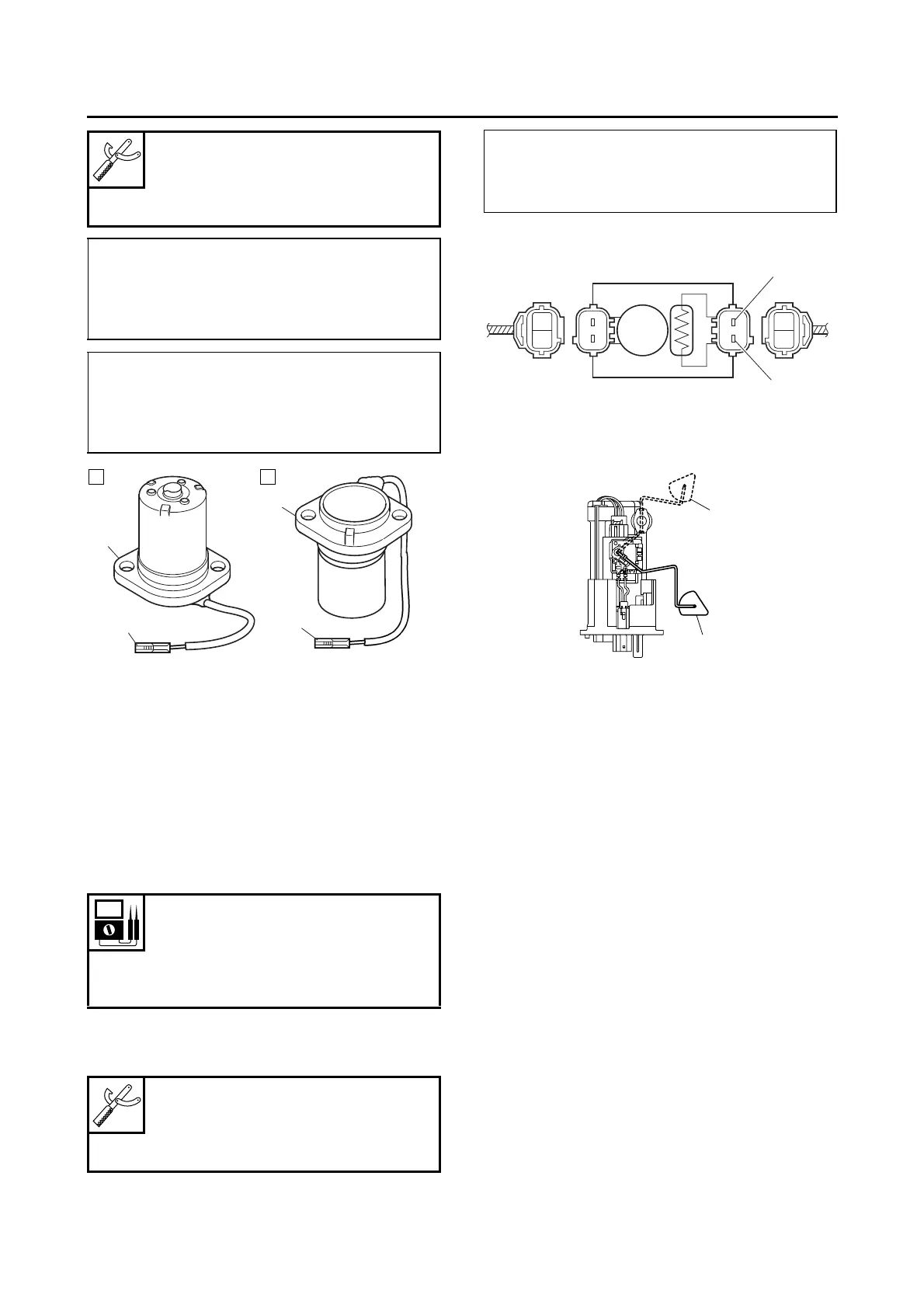
CHECKING THE FUEL SENDER
1. Remove:
• Fuel pump
(from the fuel tank)
2. Check:
• Fuel sender resistance
Out of specification → Replace the fuel pump
assembly.
▼▼▼▼ ▼ ▼▼▼▼▼▼▼▼▼ ▼ ▼▼▼▼ ▼ ▼▼▼▼ ▼ ▼▼▼▼▼▼▼
a. Connect the pocket tester (Ω × 10/× 100) to
the fuel sender terminals as shown.
b. Move the fuel sender float to minimum “3”
and maximum “4” level position.
c. Measure the fuel sender resistance.
▲▲▲▲ ▲ ▲▲▲▲▲▲▲▲▲ ▲ ▲▲▲▲ ▲ ▲▲▲▲ ▲ ▲▲▲▲ ▲▲▲
EAS29040
CHECKING THE FUEL METER/FUEL LEVEL
WARNING LIGHT
This model is equipped with a self-diagnosis de-
vice for the fuel level detection circuit.
1. Check:
• Fuel meter/fuel level warning light “1”
(Turn the main switch to “ON”.)
Warning light comes on for a few seconds,
then goes off → Warning light is OK.
Warning light does not come on → Replace
the meter assembly.
Warning light flashes eight times, then goes
off for 3 seconds in a repeated cycle (mal-
function detected in fuel sender) → Replace
the fuel pump assembly.
Pocket tester
90890-03112
Analog pocket tester
YU-03112-C
Minimum level position “A”
• Positive tester probe →
white “1”
• Negative tester probe →
body ground “2”
Maximum level position “B”
• Positive tester probe →
white “1”
• Negative tester probe →
body ground “2”
Fuel sender
Sender unit resistance (full)
19.0–21.0 Ω
Sender unit resistance (empty)
139.0–141.0 Ω
Pocket tester
90890-03112
Analog pocket tester
YU-03112-C
• Positive tester probe →
green/white “1”
• Negative tester probe →
black/white “2”