4-12
CYLINDER HEADS
ENG
NOTE:
NOTE:
*****************************************************
*****************************************************
NOTE:
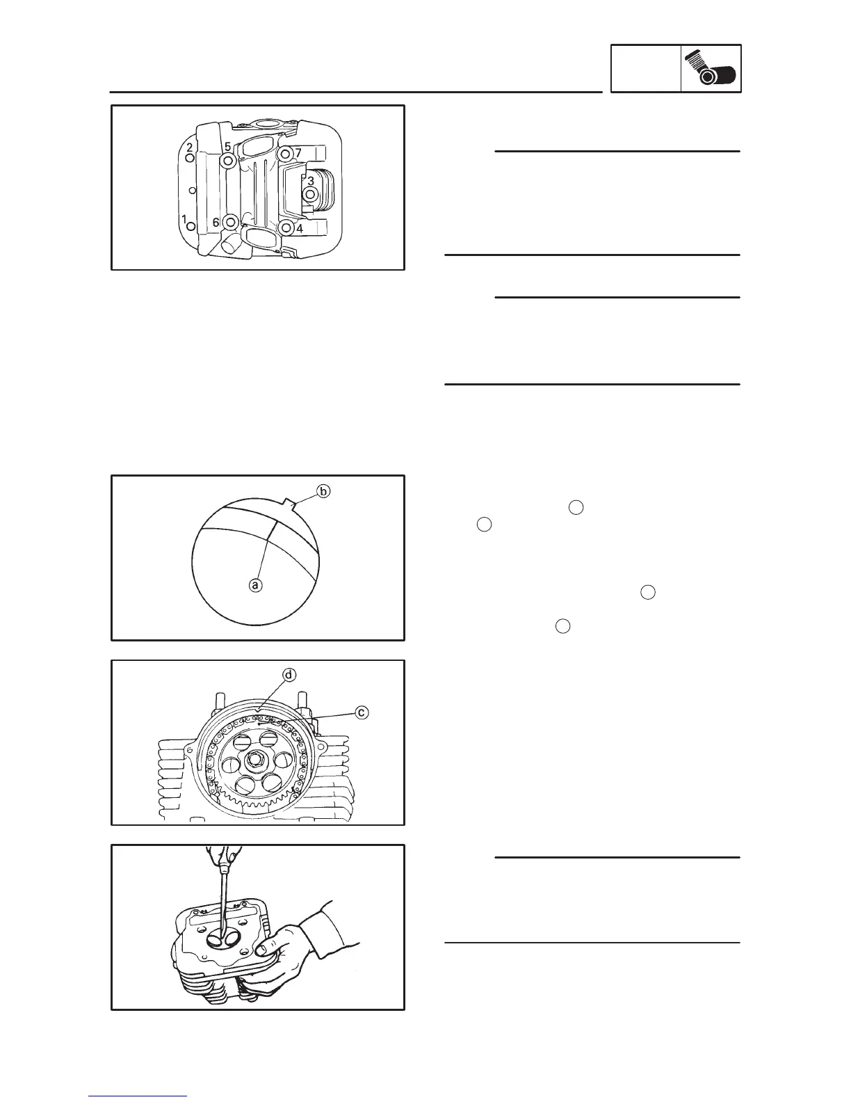
6. Remove:
S Cylinder head
D Loosen the bolts and nuts in the proper se-
quence.
D Follow the numerical order shown in the il-
lustration. Loosen each bolt 1/4 of a turn at a
time until all of the bolts are loose.
Front cylinder head
When removing the front cylinder head cam-
shafts, repeat the rear cylinder head camshafts
removal procedures. However, note the follow-
ing points.
1. Align:
S “I” mark
(with the stationary pointer)
Removal steps:
D Turn the crankshaft clockwise 290_.
D Align the “I” mark
a
with the stationary point-
er
b
on the crankcase cover (left) when the
front piston is at TDC on the compression
stroke.
D When the “I” mark is aligned with the station-
ary pointer the punch mark
c
on the cam-
shaft sprocket should be aligned with the sta-
tionary pointer
d
on the cylinder head.
D The front piston is at TDC on the compres-
sion stroke when there is clearance at both of
the rocker arms. If there is no clearance then
turn the crankshaft clockwise one full turn.
D Check that the front piston is at TDC in the
compression stroke.
CYLINDER HEAD INSPECTION
1. Eliminate:
S Carbon deposits (from the combustion
chambers)
Use a rounded scraper.
Do not use a sharp instrument to avoid damag-
ing or scratching:
D Spark plug threads
D Valve seats
2. Inspect:
S Cylinder heads
Scratches/damage Replace.