7-34
SIGNAL SYSTEM
ELEC
1. Horn switch
Refer to “SWITCH INSPECTION”.
Replace the handlebar switch (left).
NO CONTINUITY
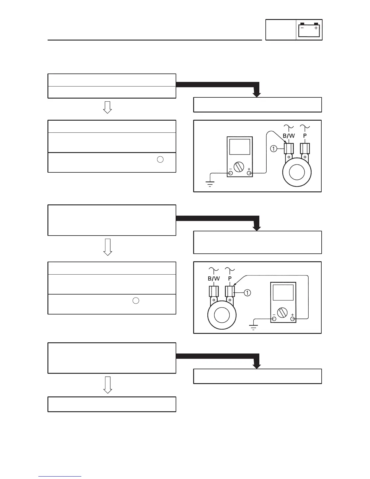
2. Voltage
S Connect the pocket tester (DC 20 V) to the
horn lead.
Tester (+) lead Black/White lead
Tester (–) lead Frame ground
CONTINUITY
S Turn the main switch to “ON”.
S Check the voltage (12 V) of the “Black/
White” lead at the horn terminal.
The wiring circuit from the main switch to the
horn terminal is faulty, repair it.
OUT OF SPECIFICATION
MEETS
SPECIFICATION
1
3. Voltage
S Connect the pocket tester (DC 20 V) to the
horn at the “Pink” terminal.
Tester (+) lead Pink lead
Tester (–) lead Frame ground
S Turn the main switch to “ON”.
S Check the voltage (12 V) of the “Pink” lead
at the horn terminal.
Replace the horn.
OUT OF SPECIFICATION
Adjust or replace the horn.
MEETS
SPECIFICATION
1
EB806020
SIGNAL SYSTEM CHECK
1. If the horn fails to sound: