4-58
CRANKSHAFT AND CONNECTING RODS
ENG
*****************************************************
CAUTION:
NOTE:
NOTE:
5. Inspect:
Crank pin surfaces
Bearing surfaces
Wear/scratches Replace.
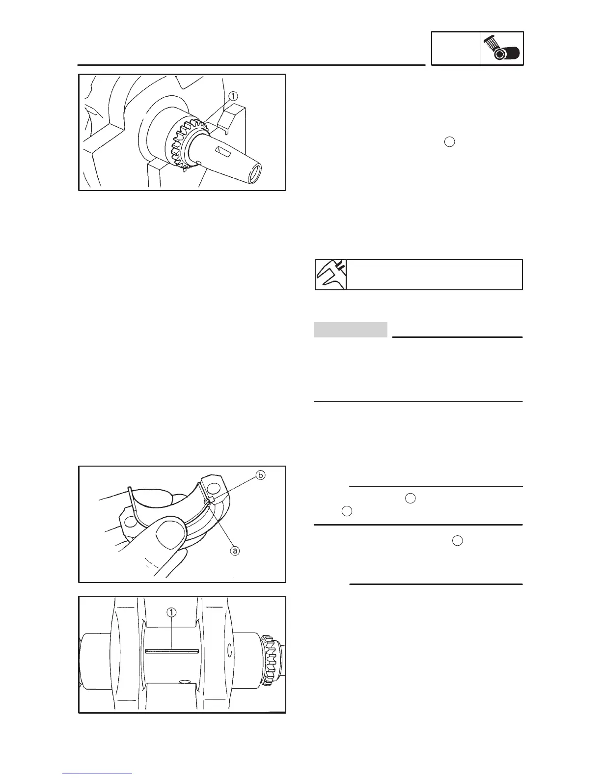
6. Inspect:
Timing chain sprockets
1
Damage/wear Replace the crankshaft.
7. Measure:
Oil clearance (crank pin)
Out of specification Replace the bear-
ing.
Oil clearance (crank pin):
0.026 0.050 mm
Measurement steps:
Do not interchange the bearings and con-
necting rods. To obtain the correct oil clear-
ance and to prevent engine damage they
must be installed in their original positions.
Clean the bearings, crank pins and bearing
portions of the connecting rods.
Install the upper half of the bearing into the
connecting rod and the lower half of the bear-
ing into the connecting rod cap.
Align the projection
a
of the bearing with the
notch
b
of the connecting rod and its cap.
Put a piece of Plastigauge
1
on the crank
pin.
Assemble the connecting rod halves.
Do not move the connecting rod or crank-
shaft until the oil clearance measurement
has been completed.
Apply molybdenum disulfide grease to the
bolts, threads and nut seats.
 Loading...