5.7 CP-215 Repeaters
5-41
5
Standard System Configuration for Optical Repeater-TS
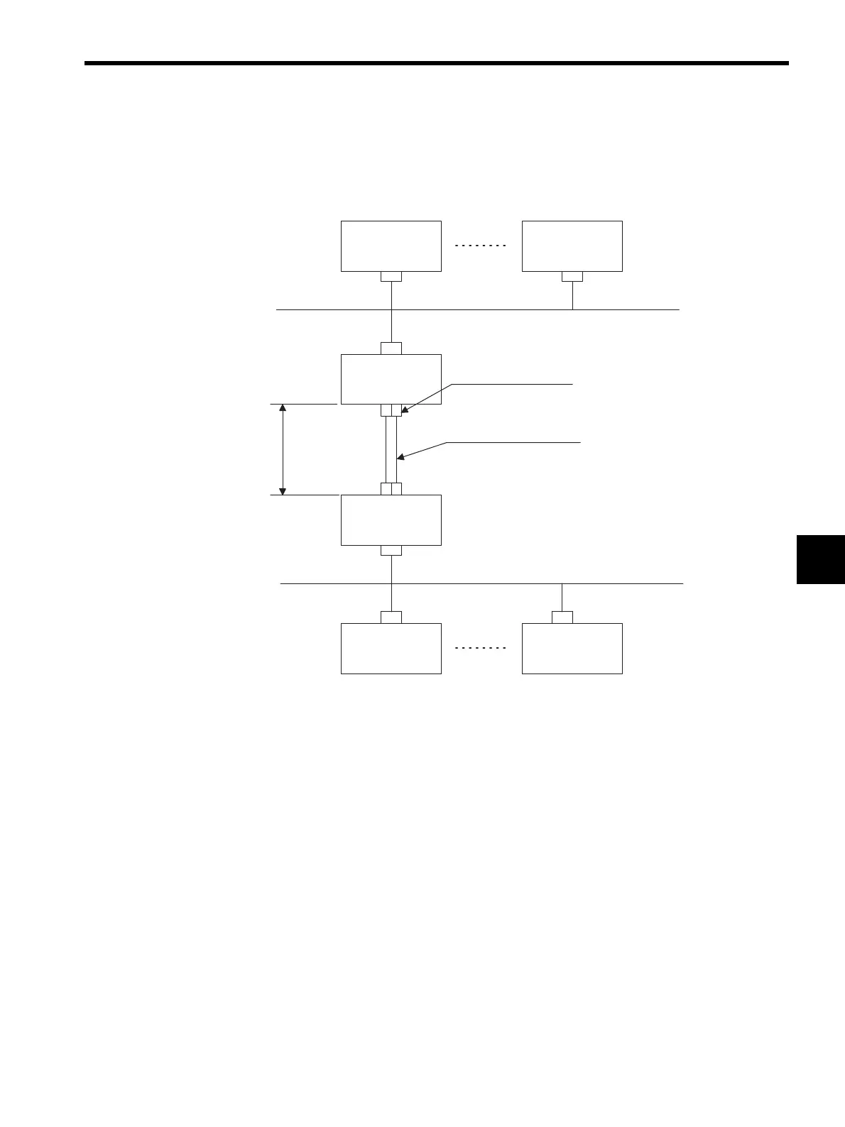
The following example shows the standard system configuration using two Optical Repeat-
ers.
Fig. 5.9 Standard System Configuration for Optical Repeater-TS
Dual System Configuration
The following example shows a Dual system configuration for Repeaters.
If the CP-215 transmission line consists of a simplex system, the respective Repeaters on the
upstream side of systems A and B can be switched to primary or standby Repeaters by using
the system A/B changeover contact input signal (CN2). Switch the current primary Repeat-
ers to standby Repeaters first, then switch the current standby Repeaters to primary Repeat-
ers. Be sure to follow this switching sequence. Set the system A/B changeover contact input
signal for the Repeaters on the downstream side to ON all the time, or turn ON pin 7 of
SW1.
When the Repeaters and transmission cables in the primary system fail, the standby system
will switch to the primary system to recover transmissions. A transmission error will exist
from the time the failure occurs until the standby system switches to the primary system.
The difference in the Repeater-to-Repeater cable length between systems A and B must be
less than 2 km.
CN4
CN1
CN3
CN1
CN4
CN3
Station
Repeater-TS
Repeater-TS
CP-215 branch bus
CP-215 main bus
TS2: 2 km
TS5: 5 km
CN3, CN4: FC connector
Two-core optical fiber cable
(TS2: Gl-50/125, 850 m, 200 MHzkm, 2.5 to 3 dB/km)
(TS5: Gl-50/125, 1,300m, 200 MHzkm, 0.7 to 1 dB/km)
170 m max. per 30 stations
170 m max. per 30 stations
Station
Station Station