7.2 Part Names
7-5
7
7.2 Part Names
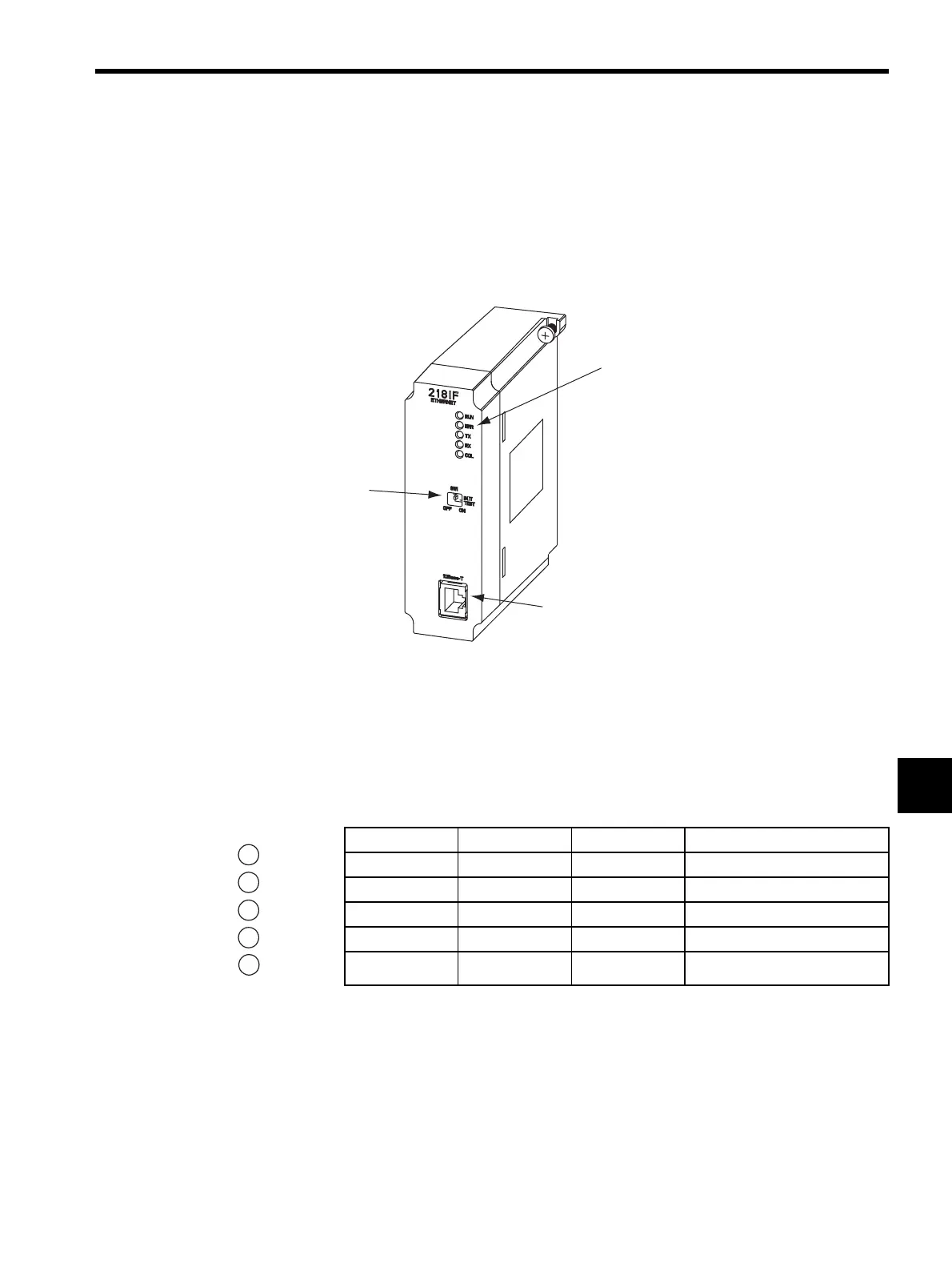
This section explains the LED indicators and switch settings for the 218IFA Module.
7.2.1 218IF Module
LED Indicators
When the Module is operating normally, the RUN LED indicator will be lit and the ERR
LED indicator will not be lit. If a failure occurs, the RUN LED indicator will turn OFF and
the ERR LED indicator will light or flashes. The TX LED indicator and RX LED indicator
will light when sending/receiving data.
LED indicators
10 Base-T
DIP switch
Label Name Color Status when Lit
RUN Run Green
Operating normally
ERR Error Red
Failure occurred (See next page.)
TX 218TX Green
218IF sending data
RX 218RX Green
218IF receiving data
COL Collision Green
218IF detecting collision
RUN
ERR
TX
RX
COL