8 Example Communications Module Applications
8.6.1 System Configuration
8-34
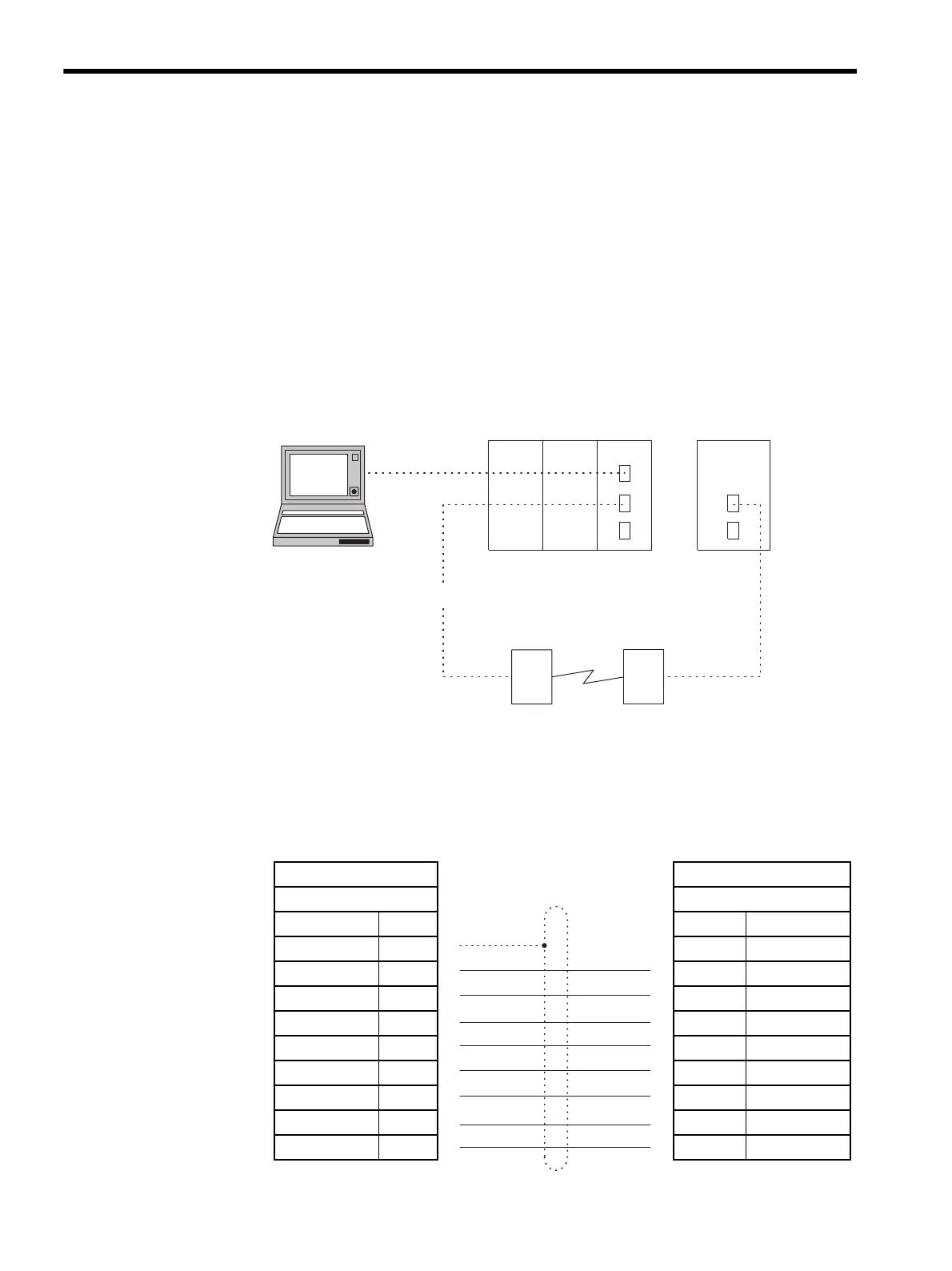
8.6 Modem-to-Modem Connection
This section explains MEMOBUS Master/Slave communications with two modems.
8.6.1 System Configuration
The standard serial port (Port 1) of an MP930 located a distance away from the 217IF Mod-
ule is configured as a modem-to-modem system.
The engineering environment is provided by connecting the MPE720 Programming Device
to the CN1 port of the 217IF.
8.6.2 Cable Specifications
217IF Module ↔ Modem
MP930 ↔ Modem Connection Cables
MP930MP920
PS-01 CPU-01 217IF
Engineering
MPE720
MEMOBUS
RS-232C
Modem Modem
217IF Module Modem
D-sub 9-pin D-sub 9-pin
Signal Name Pin No. Pin No. Signal Name
FG
11
FG
TXD
22
TXD
RXD
33
RXD
RTS
44
RTS
CTS
55
CTS
DSR
66
DSR
SG
77
SG
N.C.
88
N.C.
DTR
99
DTR