5 215IF Module
5.1.2 System Configuration Using the Relay Function
5-4
5.1.2 System Configuration Using the Relay Function
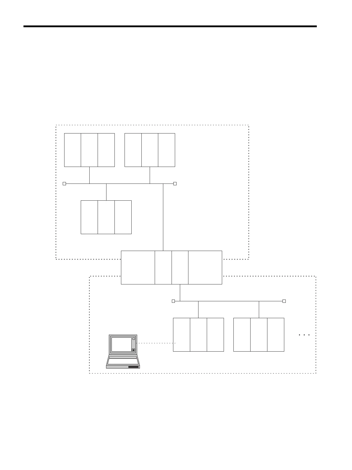
The following diagram shows an example of a system in which two networks are linked
using 215IF Modules.
When the 215IF Module relay function is used, information can be exchanged with the Con-
trollers connected to a different network segment, and the entire system can be managed and
controlled by the MPE720 Programming Device.
Data can be transferred between Network 1 and Network 2 via ST#10 and ST#20. Informa-
tion about all the Controllers can be managed from the MPE720 Programming Device using
the network numbers and station numbers.
215IF
ST#1
215IF
ST#2
215IF
ST#3
215IF
ST#20
215IF
ST#10
215IF 215IF
ST#21 ST#22
MPE720
RS-232C
Network 1
(NW#1)
(NW#2)
Network 2