6.4 Cables
6-11
6
6.4.2 RS-422/485 Interface Cables
• The power system, control system, and electrical system, as well as the transmission system, must
be wired separately.
• The RS-422/485 interface of the 217IF Module is an MR-8-pin connector (CN3).
• The maximum length of the RS-422/485 cable is 300 meters. This cable should be as short as pos-
sible.
• The RS-422/485 interface of the 217IF Module is not isolated. A malfunction may sometimes
occur, due to noise from the connected terminals. If noise is a problem, use a shielded cable or a
modem to reduce the noise.
• With the RS-422, insert terminating resistances as required. Be sure to insert terminating resis-
tance at the ends of the line.
• With the RS-485, use terminating resistances at both end stations of the transmission line.
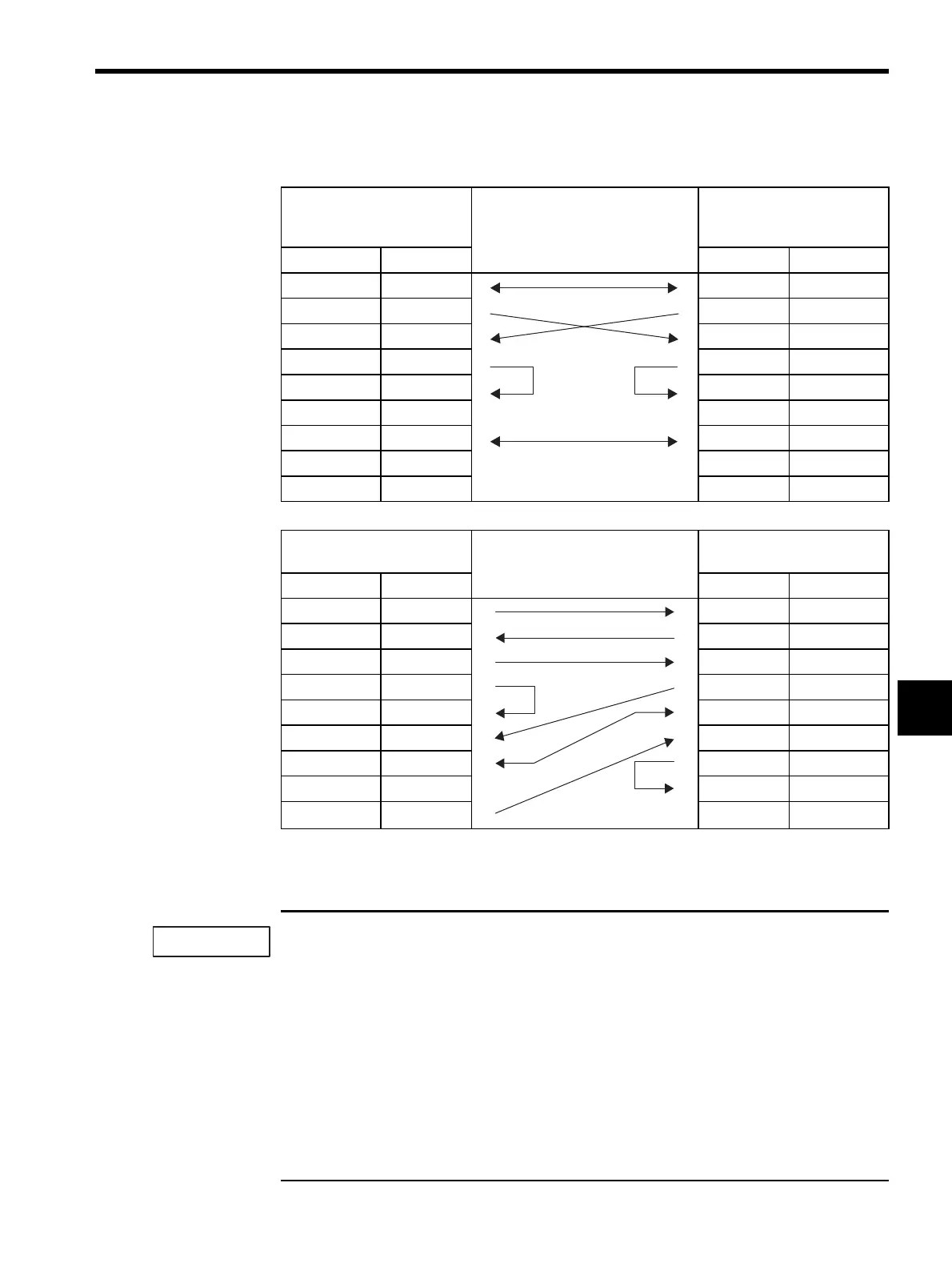
Table 6.5 217IF RS-232C Transmission Line Connections
MP920 217IF (CN1, CN2) Cable Connection and Signal
Direction
Remote Station
(D-sub 9-pin)
(Yaskawa Specifications)
Signal Name Pin No. Pin No. Signal Name
FG
11
FG
SD (TXD)
22
SD (TXD)
RD (RXD)
33
RD (RXD)
RS
44
RS
CS (CTS)
55
CS (CTS)
DR (DSR)
66
DR (DSR)
SG
77
SG
CD
88
CD
ER (DTR)
99
ER (DTR)
MP920 217IF (CN1) Cable Connection and Signal
Direction
PC/AT Compatible Personal
Computer
Signal Name Pin No. Pin No. Signal Name
FG
11
FG
SD (TXD)
22
SD (TXD)
RD (RXD)
33
RD (RXD)
RS
44
RS
CS (CTS)
55
CS (CTS)
DR (DSR)
66
DR (DSR)
SG
77
SG
CD
88
CD
ER (DTR)
99
ER (DTR)
IMPORTANT