4.2 Communications Port Settings
4-7
4
4.2.2 CP-215 Communications Port Settings
Setting CP-215PC/AT Cards
CP-215 PC/AT Cards are set when engineering is performed with the MPE720 via the 215IF.
Install the card in an unused ISA slot of the personal computer.
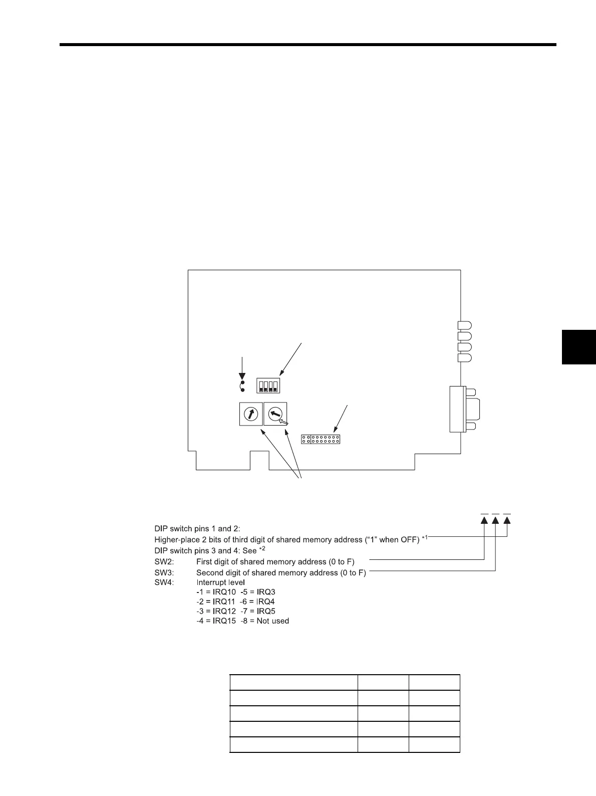
Refer to the setting example given below.
Setting Example
Shared memory address: 0CC000H
Interrupt level: IRQ11
* 1. Specify the value of the third digit of the shared memory address
according to the combinations of pins 1 and 2 of the DIP switch as
shown below.
SW1
SW2 SW3
SW4
ON
OFF
1234
F
E
D
C
B
A
9
8
7
6
4
3
2
1
0
5
F
E
D
C
B
A
9
8
7
6
4
3
2
1
0
5
215IF/ATF87215-90000-S01
Jumper lead
DIP switch (pins 1 to 4)
Rotary switches (setting 0 to F)
LED
LED1
LED2
LED3
LED4
Plug switch (1 to 8)
0CC000H
Shared Memory Address Pin 1 Pin 2
(0000-3FFF) H
ON ON
(4000-7FFF) H
ON OFF
(8000-BFFF) H
OFF ON
(C000-FFFF) H
OFF OFF