Appendix D Wiring Communications
D.2.2 Panel-to-Panel Cables
D-16
D.2.2 Panel-to-Panel Cables
The following table shows the panel-to-panel cables used for communications.
Always use the specified cables. Otherwise, the communications system will fail to provide
its full performance.
When bending a communications cable, be sure that the bending radius is at least 10 times
the finished outer diameter of the cable.
D.2.3 Wiring Separation
• House the shielded communications cables in a low-voltage circuit duct that is different
from general operation circuit ducts. If this is not possible, keep the low-voltage circuits
at least 100 mm away from the general control circuits.
• Likewise, keep the shielded communications cables at least 300 to 1,200 mm from the
main circuits.
D.2.4 Shield Treatment
• Ground the shield at one point only for panel-to-panel cables.
• Using a ground wire of 8 mm
2
or greater, ground the shielded ground trunk cable to an
independent ground pole with a ground resistance of 100Ω or less.
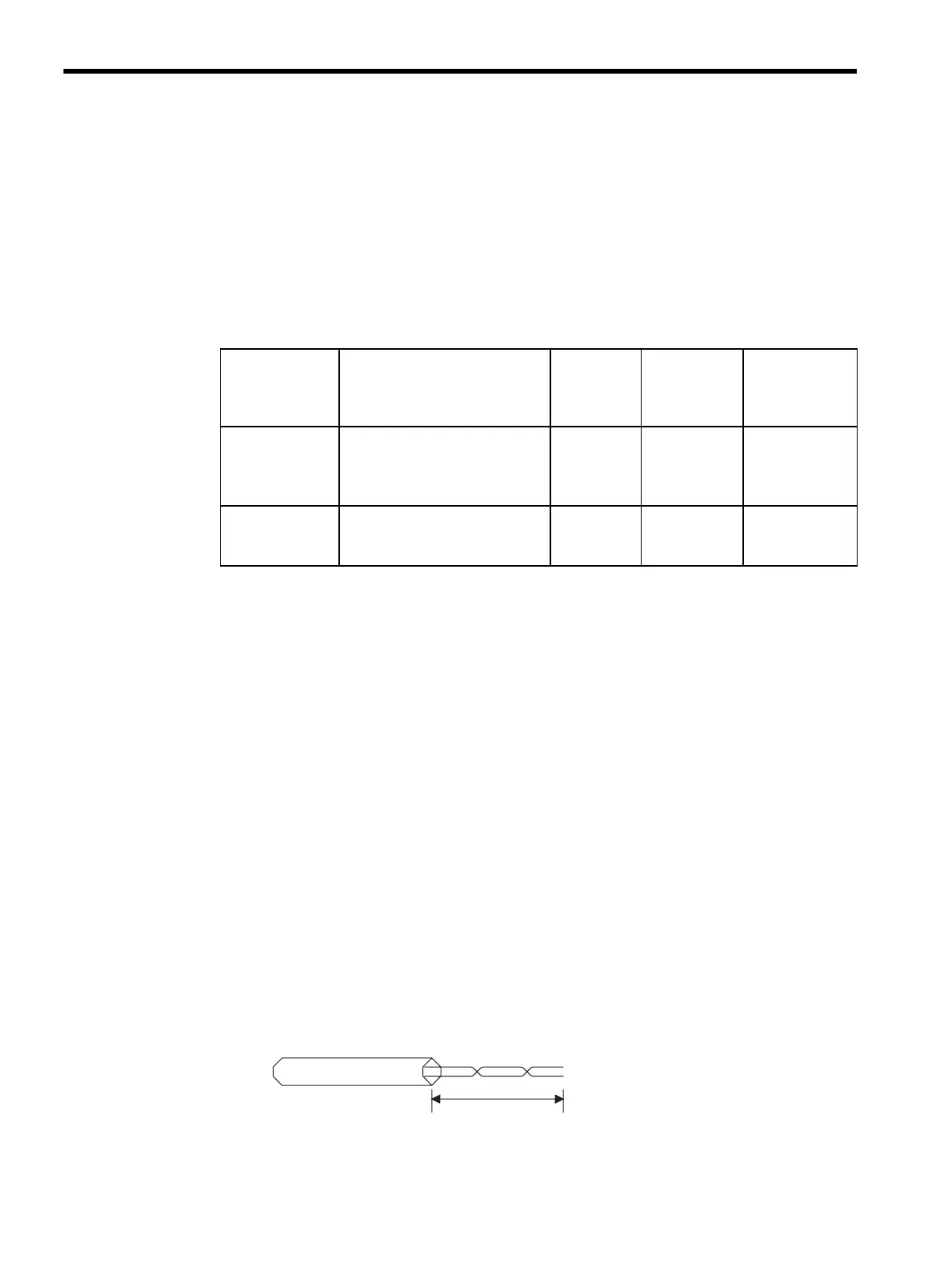
D.2.5 Exposed Conductor Length
• The exposed conductor length of each panel-to-panel twisted-pair cable should be as
short as possible (100 mm or less).
• The characteristic impedance of the exposed conductor section is greater than the pre-
scribed value (75Ω).
• Increasing the exposed conductor length increases transmission waveform distortion,
resulting in a transmission error.
Table D.3 Cable Bending Radius
Communications
System
Cable Type Finished
Outer
Diameter
dl (mm)
Permissible
Bending
Radius
10 dl (mm)
Applicable Duct
215IF,
217IF RS-485
Twisted-pair cable:
YS-IPEV-S (Cu), 1P × 1.25 mm,
manufactured by Fujikura Corpo-
ration
8.6 86 min.
Low-voltage
duct
CP-215
Repeater
Coaxial cable:
5C-2V (Cu, Fe)-ZV, manufac-
tured by Fujikura Corporation
12.0 120 min.
Low-voltage
duct
100 mm max.
Twisted-pair cable