6 217IF Module
6.4.1 RS-232C Interface Cables
6-10
6.4 Cables
This section explains the cable specifications for communications using the 217IF Module.
6.4.1 RS-232C Interface Cables
1. The power system, control system, and electrical system, as well as the transmission system, must
be wired separately.
2. There are two D-sub 9-pin (CN1, CN2) connectors for the RS-232C interface on the 217IF Module.
3. The maximum length of the RS-232C cable is 15 meters. This cable should be as short as possible.
4. The RS-232C interface of the 217IF Module is not isolated. A malfunction may sometimes occur
due to noise from the connected terminals. If noise is a problem, use a shielded cable or a modem to
reduce the noise.
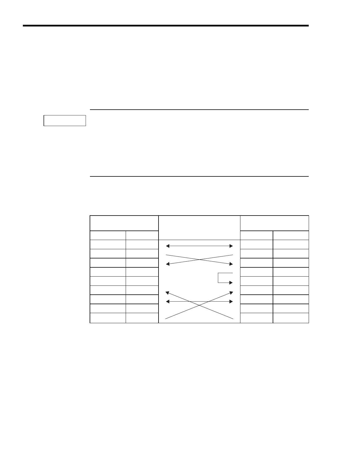
The following table shows the 217IF RS-232C transmission line connections of 217IF Mod-
ule.
Table 6.4 217IF RS-232C Transmission Line Connections
MP920 217IF (CN1, CN2) Cable Connection and Signal
Direction
Remote Station
(D-sub 25-pin)
Signal Name Pin No. Pin No. Signal Name
FG
11
FG
SD (TXD)
22
SD (TXD)
RD (RXD)
33
RD (RXD)
RS
44
RS
CS (CTS)
55
CS (CTS)
DR (DSR)
66
DSR (DR)
SG
77
SG
CD
88
CD
ER (DTR)
920
DTR (ER)
IMPORTANT