5.1 System Configuration
5-3
5
5.1 System Configuration
This section gives an overview of the system configuration with 215IF Modules.
5.1.1 Standard System Configuration
Shown below is a simple system example in which a single network is configured for a
215IF System.
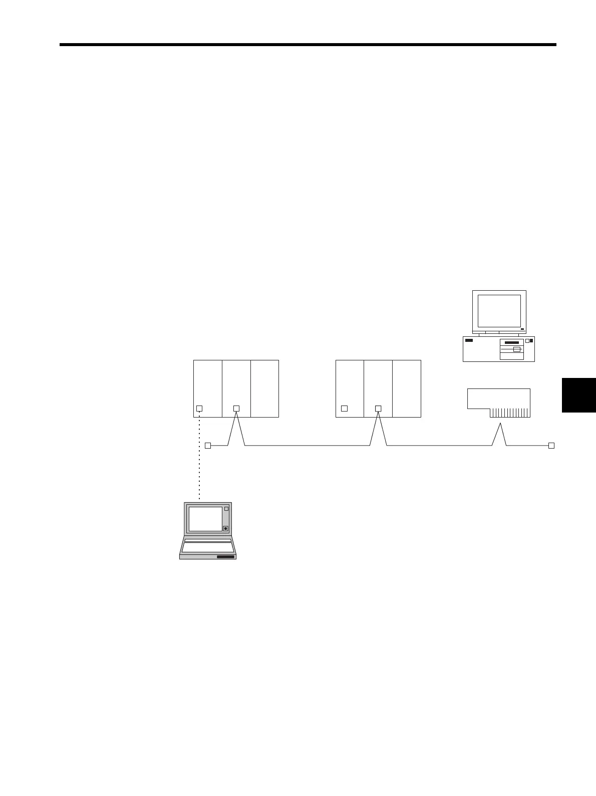
The following diagram shows an example of a MPE720 Programming Device with two
MP920 Units and a 215IF Card installed, connected by a 215IF Connection Cable. The Pro-
gramming Device can also be connected using the serial port of an MP920 CPU Module.
The 215IF Modules are managed using station numbers (ST#n). A different station number
must be assigned to each Module. The Modules cannot be linked if the same station number
is assigned to more than one Module.
MPE720
ST#3
MP920 215IF SVA MP920 215IF SVB
ST#2ST#1
+
215IF Connection Cable
RS-232C
MPE720
215 IF/AT