5 215IF Module
5.2.2 Setting Switches
5-6
The following table describes the operation of the LED indicators when a failure has
occurred.
Note: The number in parentheses ( ) after “Flashing” indicates the number
of flashes.
5.2.2 Setting Switches
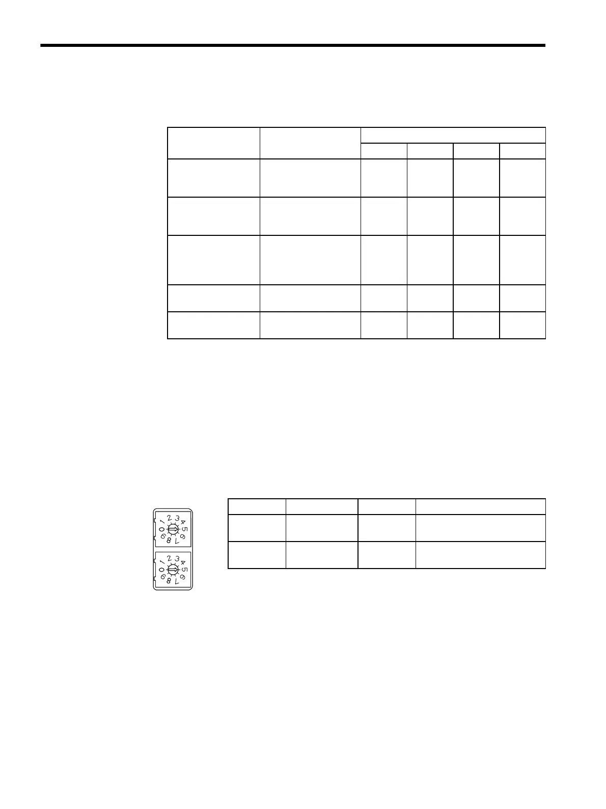
Rotary Switches (SW1, SW2)
SW1 and SW2 set the address for 215IF Module communications. SW1 sets the first digit;
SW2 sets the second digit. Station addresses are numbered 1 to 64. These switches are effec-
tive only when the INIT switch is ON.
Failure Meaning LED Indicators
RUN ERR TX RX
PROM Checksum
Error
A PROM checksum
error was detected dur-
ing online self-diagnosis.
Not lit Flashing
(1)
Not lit Not lit
Module Hardware
Error
A hardware error was
detected during online
self-diagnosis.
Not lit Flashing
(2)
Not lit Not lit
CPU Interface Error A data transmission error
was detected between
Module and CPU during
online self-diagnosis.
Not lit Flashing
(3)
Not lit Not lit
Transmission Error A normal transmission
error was detected.
Lit Lit Lit Lit
Watchdog Timer
Error
A watchdog timer error
was detected.
Not lit Flashing
(15)
Not lit Not lit
Label Name Setting Operation
ADRS
× 1
Address × 1 1 to 10 The first digit of the station
address
ADRS
× 10
Address ×10 1 to 10 The second digit of the station
address
SW1
SW2
ADRS
X1
ADRS
X10