Appendix D Wiring Communications
D.6.3 Crystal Fiber Cords for Long Wavelength
D-36
D.6.3 Crystal Fiber Cords for Long Wavelength
* Temporary tension applied when the cable is laid. The maxim allowable tension that can be
applied to the neck of the optical connector is 2 kg. The applicable optical connector is FC type
(complying with JIS C 5970 F01).
Note: 1. For cable specifications other than those shown above, contact your Yaskawa representa-
tive.
2. If cables manufactured by another company are to be used, present the above optical fiber
core specifications to that company.
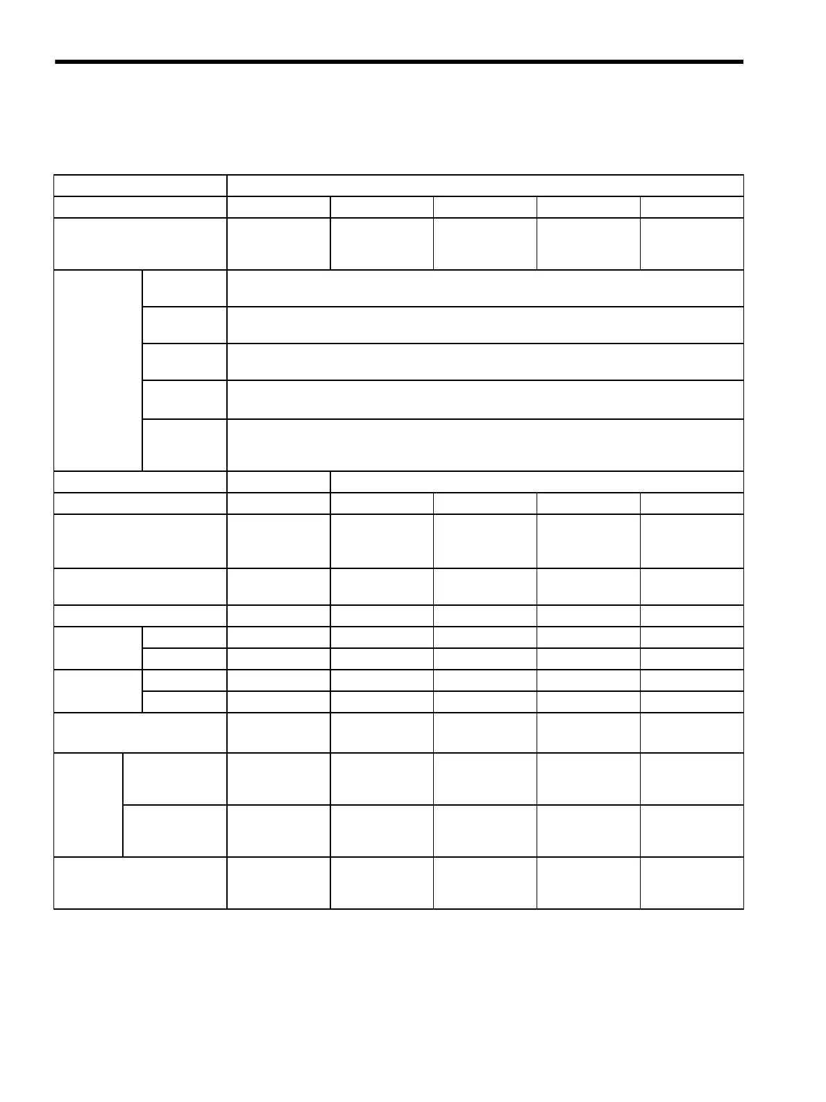
Table D.5 Cable Specifications (GIñ50/125, l = 1,300 nm)
Item Specifications
Cable Type Single-core cord Indoor cable Indoor cable Outdoor cable Outdoor cable
Representative Model
(Manufactured by Sumitomo
Electric Industries, Ltd.)
CSV-EG-5/0702 2GI-C-V-NM 2GI-GS-E-NM 2GI-L-4C-LAP 2GI-C-LAP
Optical Fiber
Core
Specifications
Optical Fiber
Type
Graded-index (GI) fiber
Transmission
Loss
0.7 dB/km max. (λ = 1300 nm)
Transmission
Bandwidth
200 MHz⋅km min.
Core and
Clad
Material: Crystal glass, Diameter: 50 ±3 µm
Material: Crystal glass, Diameter: 125 ±3 µm
Numerical
Aperture
(NA)
0.21 ±0.02
Number of Cores 12
Sheath Black PVC Black PVC Black PE Black PE Black PE
Tension Member None 1.2-mm-dia. FRP 4.5-mm-dia. FRP 2.3-mm-dia. cop-
per wire with PE
insulation
1.0-mm-dia.
copper wire with
PE insulation
Finished Outer Diameter
(mm)
3 11141212
Approximate Mass (kg/km) 9 110 140 130 115
Storage
Temperature
Maximum 0°C0°C-20°C-20°C0°C
Minimum 60°C60°C60°C60°C60°C
Operating
Temperature
Maximum 0°C0°C-20°C-20°C0°C
Minimum 60°C60°C60°C60°C60°C
Maximum Allowable Tension
(kg)
*
15 50 150 150 50
Allowable
Bending
Radius
(mm)
Tem p o rary
Bending (No
Load)
30 120 450 120 120
Long-term
Bending (No
Load)
60 240 450 240 240
Maximum Allowable
Temporary Lateral Pressure
(kg/50 mm)
None None 150 100 100