5 215IF Module
5.7.3 Specifications Common to All CP-215 Repeaters
5-44
System Configuration Using Star Connections
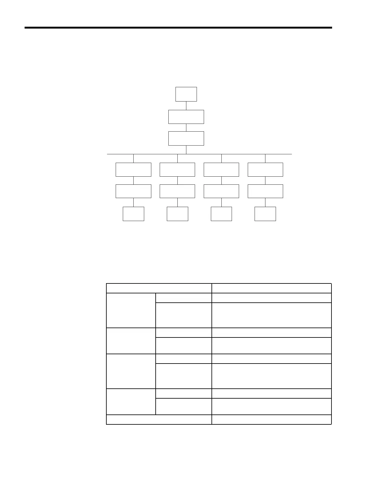
The following example shows a system configuration using star connections.
Fig. 5.12 System Configuration Using Star Connections
5.7.3 Specifications Common to All CP-215 Repeaters
Power Supply
ST#5
Up to foru Repeaters can be connected
between two stations.
In the start connection method,
Repeaters for branch lines are radially
connected from the electrical bus.
ST#4 ST#3 ST#2
ST#1
Repeater
Repeater
Repeater
Repeater
Repeater
Repeater
Repeater
Repeater
Repeater
Repeater
CP-215 electrical bus
1st
2nd
1st
2nd
Item Specifications
Rated Input
Voltage
24-VDC Models 24 VDC ±20% (19.2 to 28.8 VDC)
100-VAC, 200-VAC,
100-VDC Models
100/115 VAC ±15% (85 to 132 VAC, 47 to 63 Hz)
100 VDC -10%, +40% (90 to 140 VDC)
200 VAC ±15% (170 to 230 VAC, 47 to 63 Hz)
Power
Consumption
24-VDC Models 5 W
100-VAC, 200-VAC,
100-VDC Models
10 W
Input Inrush
Current
24-VDC Models 5 A peak at 24 VDC
100-VAC, 200-VAC,
100-VDC Models
15 A peak at 100 VDC
15 A peak at 100 VAC
30 A peak at 200 VAC
Overcurrent
Protection
24-VDC Models With built-in 1-A fuse
100-VAC, 200-VAC,
100-VDC Models
With built-in 2-A fuse
Holding Time 10 ms or less