Appendix B 218IF Messages
B.1.3 MEMOBUS ASCII Mode
B-16
B.1.3 MEMOBUS ASCII Mode
With ASCII communications, binary communications data is converted to ASCII before
being transmitted and received.
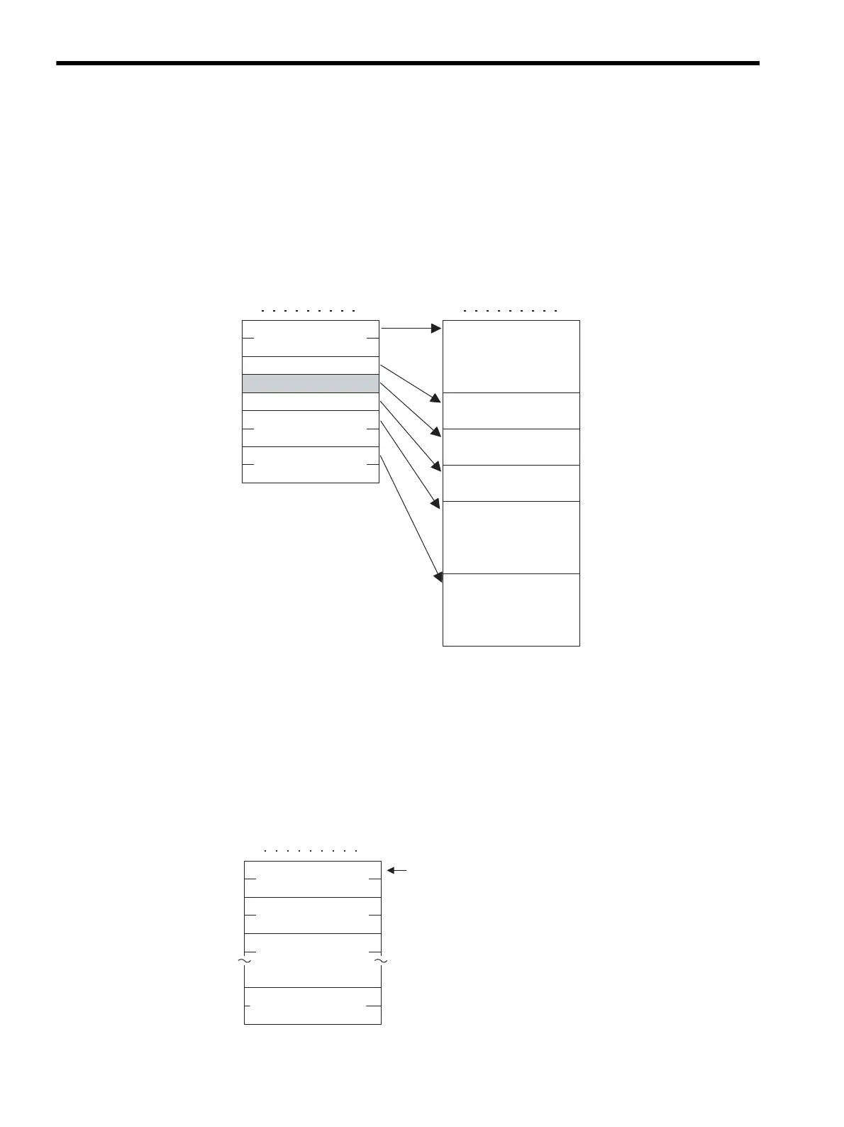
The following diagram shows an example of binary to ASCII conversion. As shown in the
example, 8-bit data is converted to two ASCII characters (7 bits). The example shows only
the conversion of the application data. However, in actual conversion, the EIF header is also
converted to ASCII.
B.1.4 General-purpose Message Binary Mode
In general-purpose message mode, the values for the Controller holding registers (MW reg-
isters) are set as is in the application data following the EIF header part, and data is transmit-
ted and received.
Binary Mode
MFC
SFC
CPU No.
20H
03H
07H
00H
12H
00H
6BH
03H
00H
30H
37H
30H
30H
Length
MFC
32H
30H
SFC
30H
33H
CPU No.
31H
32H
30H
30H
36H
42H
30H
30H
30H
33H
Length
7
07 0
Reference No.
No of registers
Reference No.
No. of registers
(L)
(H)
n
Contents of
MW
n items of data from Controller holding registers MW
to MF+ n-1 are set and transmitted.
There is no response to the transmission.
Command
(L)
(H)
Contents of
MW+1
(L)
(H)
Contents of
MW-1
(L)
(H)
(L)
(H)
70