5.4 Cables
5-13
5
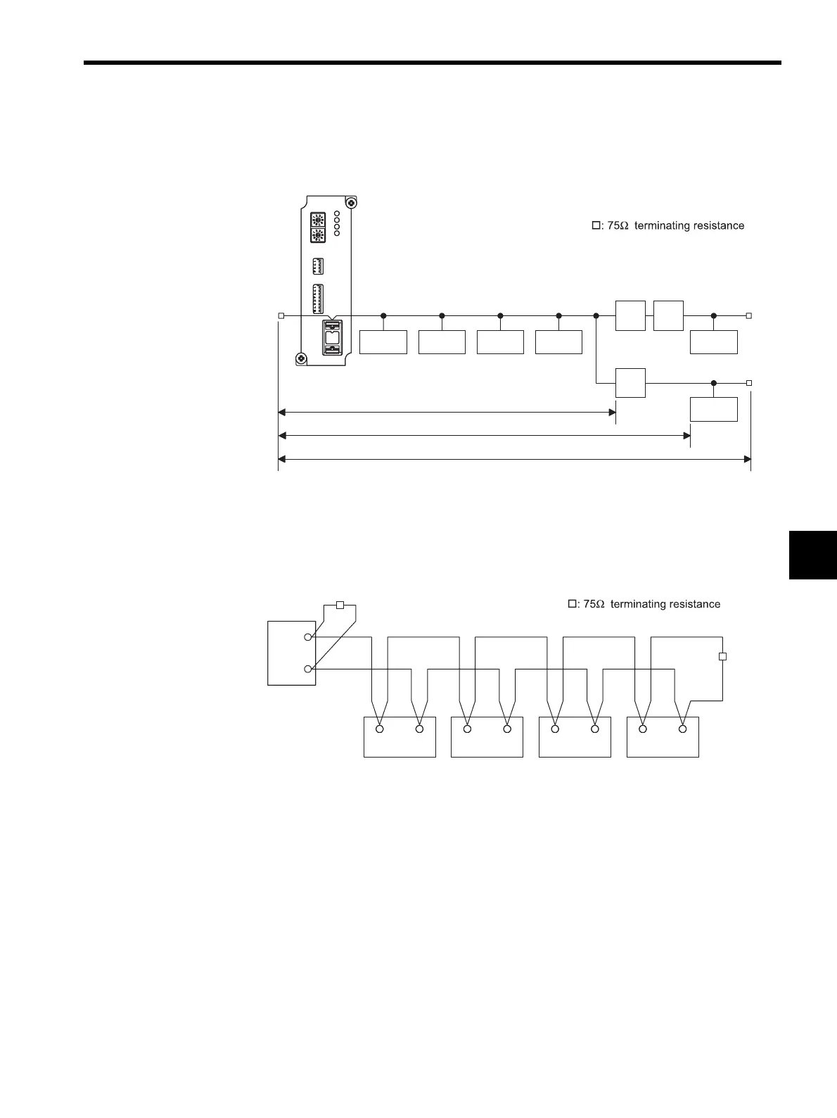
System Configuration Example
The following diagram shows a system configuration example.
CP-215 Wiring Example
The following diagram shows a wiring example for the CP-215.
5.4.2 Precautions on Wiring Communications
Following are some precautions on 215IF Modules.
Precautions
• The power system, control system, and electrical system must be wired separately.
• Provide terminating resistance at both ends of the transmission line.
• Use a YS-IPEV-S (Cu) 1P × 1.25 mm
2
(75 Ω) cable (manufactured by Fujikura Corpora-
tion) for the wiring between control panels.
• With long wires, also ground the Repeater(s).
• Any restrictions in communication performance must also be considered in connection
with the number of stations. See 2.2 Link Communications.
ON
ON
MP920
ACGC4000
CP-717 CP-316
MP920
MP920
215IF
MP920
CP-215
Repeater
Repeater
Repeater
L0
L01
L02
SIG+
SIG-
SIG+ SIG- SIG+ SIG- SIG+ SIG- SIG+
SIG-