5 215IF Module
5.4.1 215IF Connection Cables
5-12
5.4 Cables
This section explains the cable specifications for 215IF Module communications.
5.4.1 215IF Connection Cables
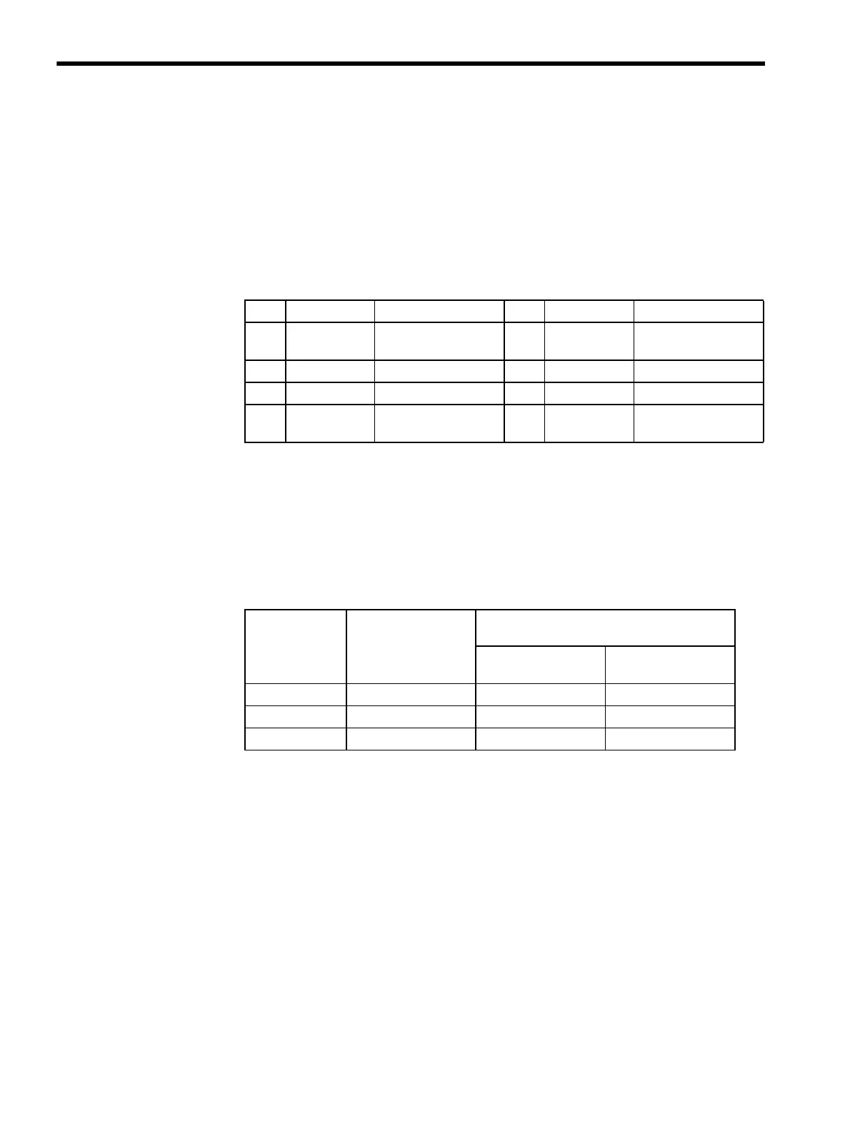
215IF Connector Pin Layout (CN1/215)
MR-8RFA4 (G) connector (manufactured by Honda Communication Industries Co., Ltd.) is
used on the Module. Use an MR-8M (G) (case: MR-8L) connector on the cable.
Calculation Example of Maximum Transmission Distance
The following table shows a calculation example for the maximum transmission distance
when 32 stations are connected.
Note: 1. L
0
is when the total length of the cables inside the control panel is
about 55 m and 20 JC215-01 Junction Boxes are used.
2. L
01
and L
02
are when 16 stations are connected on both sides of the
Repeater.
No. Signal Name Function No. Signal Name Function
1 SRD- Sending and receiving
data (-)
5 N.C. Not connected
2 N.C. Not connected 6 N.C. Not connected
3 N.C. Not connected 7 N.C. Not connected
4 N.C. Not connected 8 SRD+ Sending and receiving
data (+)
Transmission
Speed
Cable Length
between Control
Panels
L
0
: No Repeaters
Total Wiring Distance
L
01
: One Repeater L
02
: Two Repeaters
4 Mbps 170 m or less 600 m 1,100 m
2 Mbps 270 m or less 900 m 1,550 m
1 Mbps 420 m or less 1,400 m 2,350 m