D.1 In-panel Wiring
D-3
D
D.1 In-panel Wiring
D.1.1 Connection Methods
215IF Cable Connections
215IF Module
This section describes how to connect cables inside the control panel of the 215IF Module
mounted in an MP900-Series Machine Controller.
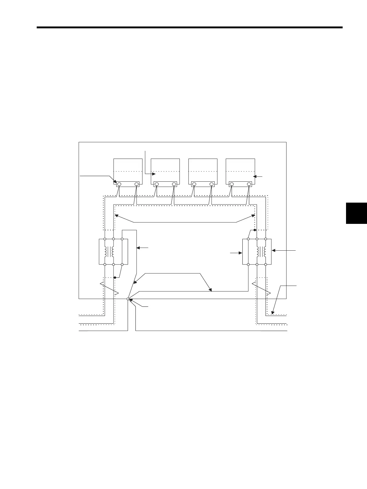
Fig. D.1 215IF Transmission Line Connection Example (JC215-01)
• For connections between Communications Interface Modules, connect the MR-8LM(G)
terminals with the same number using in-panel cables.
Connect pins 8 and 1 of the MR-8LM(G) connector to SRD+ and SRD-, respectively.
• Install the JC215-01 on the input and output sides of the control panel, and connect the
in-panel and panel-to-panel cables to the JC215-01.
• JC215-01 signal terminals: Both input and output are possible between terminals 1 and 2
or between terminals 3 and 4.
• Where the JC215-01 is installed at the end of the transmission line, always install a termi-
nating resistance (75Ω) between JC215-01 terminals 1 and 2 or between terminals 3 and
4.
• Connect only one end of each in-panel cable or panel-to-panel cable shield to terminal S
of input JC215-01 or output JC215-01, and connect terminal E to terminal Es in the con-
trol panel using a 1.25 mm
2
ground wire.
8 1
CP-316
(CP-215)
MP920
VS-676H5
VS-676H5
CN1 (/CN7)
MR-8LM (G)
215IF Module
CP-916A
Module
3
4
E
12 S
SRD+
Core unit
SRD-
SRD+
SRD-
E4
3
S2
1
VS-IPEV-SB 1P×0.3 mm
In-panel twisted-pair cable
ES
ES
1.25mm
2
min.
In-panel shielded ground wire
Input JC215-01
Output JC215-01
8 1 8 1 8 1
Transmission
line with
built-in filter
Connect this cable
shield to the ES
terminal in the
destination control
panel.