Appendix D Wiring Communications
D.1.1 Connection Methods
D-4
215IF Card for PC/AT or Compatible Computers
This section describes how to connect cables inside the control panel of the CP-215PC/AT
mounted in a PC/AT or compatible computer.
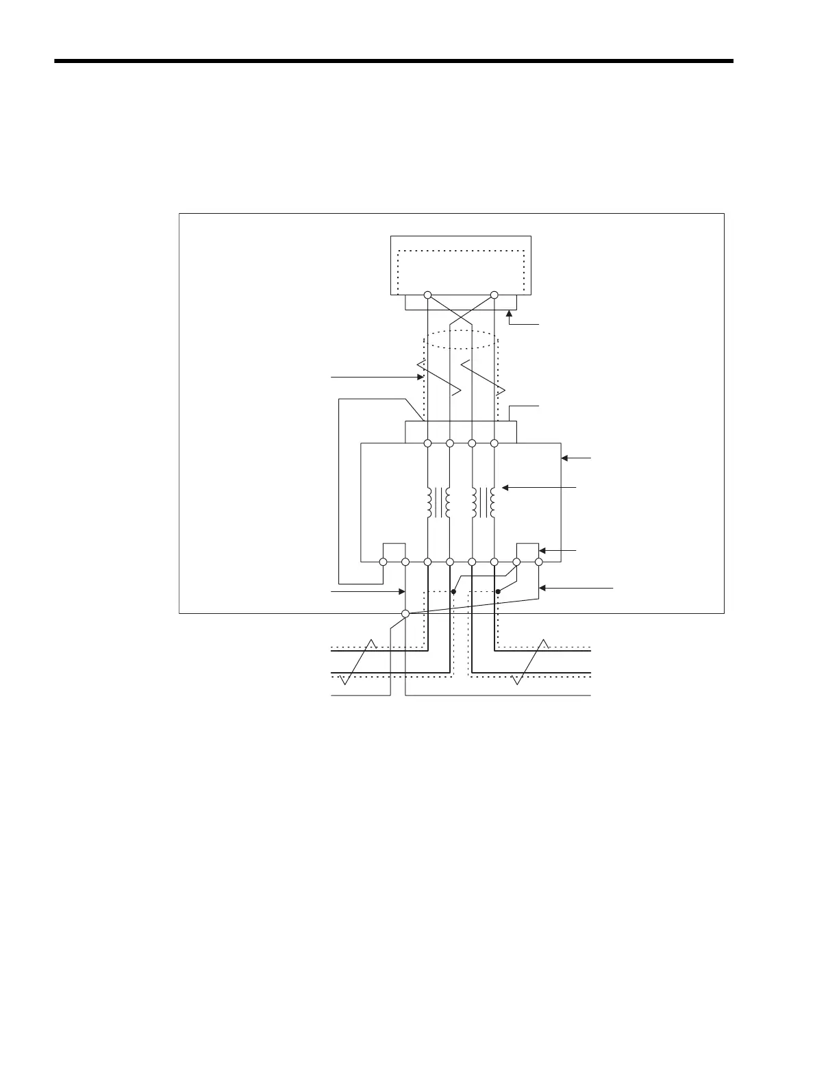
Fig. D.2 215IF Transmission Line Connection Example (JC215-02)
• Connection Method
Connect the CP-215PC/AT Card to the JC215-02 with an in-panel cable. Connect the
SRD+ and SRD- signal wires of the in-panel cable to the A+ and A- terminals (or B+ and
B- terminals), respectively.
• Terminating Resistance
If the CP-215PC/AT Card is located at the end of the transmission line, connect terminat-
ing resistances to the A+ and A- terminals (or B+ and B- terminals) of the JC215-02.
• Shield Ground Wire Treatment
Connect only one end of each in-panel cable and panel-to-panel cable shield to the S1
and S2 terminals of the JC215-02, and connect the E1 and E2 terminals to the Es termi-
nals of the control panel using a ground wire of 1.25 mm
2
or greater.
81
CP-215PC/AT
3816
A+ A- B+ B-
S1 E1 S2 E2
SRD+
SRD-
Es
SRD+
SRD-
Es
Shielded ground trunk cable 8 mm
2
min.
In-panel twisted-pair
cable YS-1PEV-SB,
3P×0.3 mm
2
min.
In-panel shielded
ground wire:
1.25 mm
2
min.
D-sub 9-pin connector
1CN MR-8LF (G)
Transmission line
filter
JC215-02
Internal
common
In-panel shielded
ground wire:
1.25 mm
2
min.
MPE720