6.2 Part Names
6-5
6
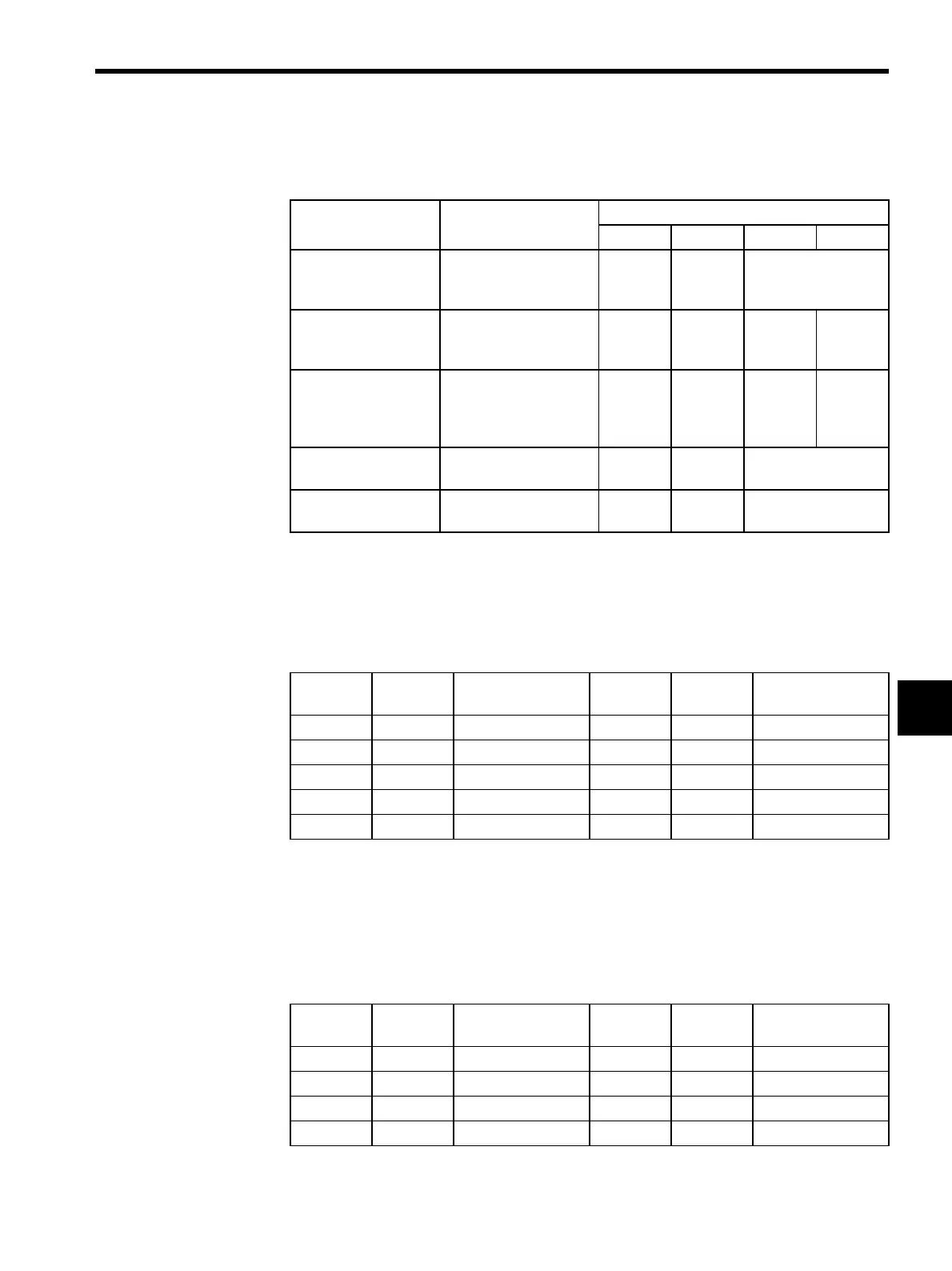
The following table describes the operation of the LED indicators when a failure has
occurred.
Note: The number in parentheses ( ) under “Flashing” indicates the number
of flashes.
Connector Pin Layout
A 17LE-13090-27 (D2AC) D-sub 9-pin female connector (manufactured by Daiichi Elec-
tronic Industries Co., Ltd.) is used as the connector on the Module.
A 17JE-23090-02 (D8B) D-sub 9-pin male connector (manufactured by Daiichi Electronic
Industries Co., Ltd.) is used as the connector on the cable.
* The terminating resistance is put on the positive (+) side.
Failure Meaning Indicators
RUN ERR TX RX
PROM Checksum
Error
A PROM checksum
error was detected dur-
ing online self-diagnosis.
Not lit Flashing
(1)
Depends on the cir-
cumstances
SRAM Error in
Module
A hardware error was
detected during online
self-diagnosis.
Not lit Flashing
(2)
Not lit Not lit
CPU Interface Error A data transmission error
was detected between
Module and CPU during
online self-diagnosis.
Not lit Flashing
(3)
Not lit Not lit
Transmission Error A normal transmission
error was detected.
Lit Lit Depends on the cir-
cumstances
Watchdog Timer
Error
A watchdog timer error
was detected.
Not lit Lit Depends on the cir-
cumstances
Table 6.1 RS-232C Connectors (CN1/RS-232C, CN2/RS-232C)
Number Signal
Name
Function Number Signal
Name
Function
1 FG Protective ground 6 N.C. Not connected
2 SD Send data 7 SG Signal ground (0 V)
3 RD Receive data 8 N.C. Not connected
4 RTS Request to send 9 N.C. Not connected
5 CS Clear to send
Table 6.2 RS-422/485 Connectors (CN3/RS-422)
Number Signal
Name
Function Number Signal
Name
Function
1 RX (-) Receive data (-) 5 TRX (+) *
2 RX (+) Receive data (+) 6 TX (-) Send data (-)
3 N.C Not connected 7 TX (+) Send data (+)
4 RXR (+) * 8 SG Signal ground