6.4 Cables
6-13
6
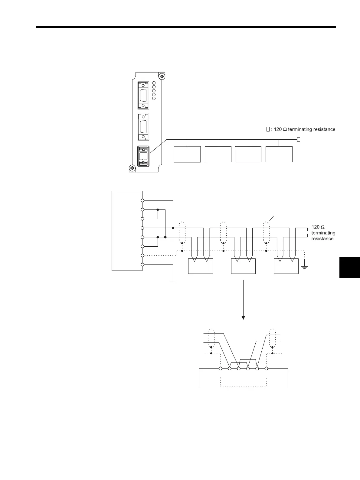
RS-485 Wiring
Note: 1. The terminating resistance will be enabled by connecting terminals
5 and 6, and terminals 1 and 4 at the CN3 interface.
2. Connect the 217IF CN3 FG connection to the FG terminal of the
Power Supply Module, using a lead wire.
CN2
CN1
RUN
ERR
TRX1
TRX2
TRX3
CN3
217IF
RS232/422
Terminal Terminal Terminal Terminal
(PLC, etc.) (PLC, etc.) (PLC, etc.)
(PLC, etc.)
RS-485
MP920
TX / RX TX / RX TX / RX
7
TX (+)
6
TX (-)
5
TXR
2
RX (+)
1
RX (-)
4
RXR
3
SH
8
SH
FG
217IF CN3
FG
Shield
1
2
For example, when a 217IF Module is
connected at intermediate position,
the wiring will be as shown below.
SH
TX
(-) (+) (-) (+)
TX RX RX
SH
367128
1
2