8 Example Communications Module Applications
8.3.2 Cable Specifications
8-18
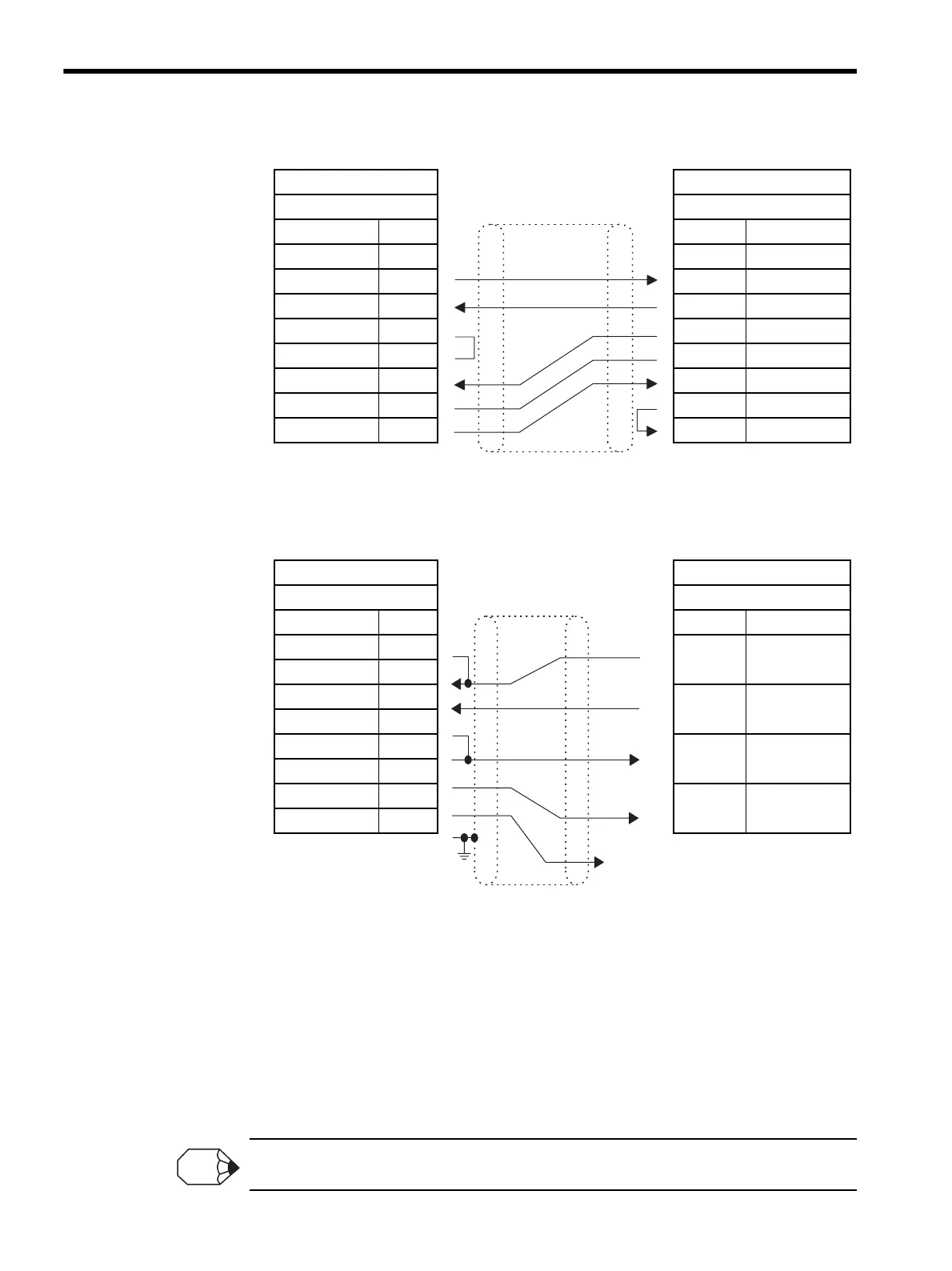
CN1 Cables
Note: Mitsubishi Electric Controller model: A1SJ71C24
CN3 Cables
* For the AJ71UC24, switch SW24, which is used to connect the terminat-
ing resistance, must be set to ON (MELSEC).
Note: 1. Mitsubishi Electric Controller models:
A1SJ71C24
AJ71UC24
A171QC24
A1SJ71UC24-R4: R2 cannot be connected.
(This is because the RS-232C 1: 1 connection address is fixed at
“0”.)
2. Connect the cable so that the terminating resistance for the 217IF
Module is connected.
Refer to 8.1.2 Cable Specifications for the MPE720 Programming Device connections.
217IF MELSEC Controller
D-sub 9-pin D-sub 9-pin
Signal Name Pin No. Pin No. Signal Name
FG
11
CD
TXD
22
RD
RXD
33
SD
RTS
44
DTR
CTS
55
SG
DSR
66
DSR
SG
77
RS
DTR
98
CS
217IF Screw Terminal Block *
MR 8-pin Signal Name
Signal Name Pin No. Left Right
RXR 4
SD A
RX (-) 1 SG
RX (+) 2
SD B
TXR 5 FG
TX (-) 6
RD A
TX (+) 7 N.C.
SG 8
RD B
SH 3
Shield
FG
To SG on
the right
Shield
INFO