8 Example Communications Module Applications
8.3.4 MELSEC Settings (AJ71UC24 Example)
8-20
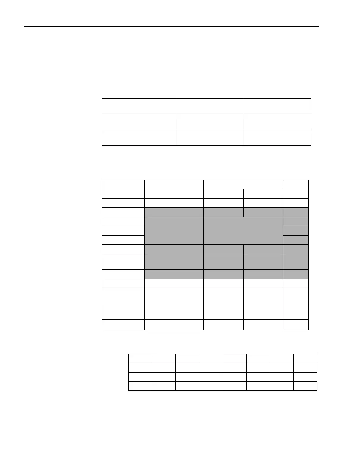
Switch Settings
Station Number Setting Switches
Set 01 to 31, but not 0. (Recommended value: 01)
Communications Specification Setting Switches (For AJ71UC24 Mod-
ules)
Note: The shaded parts show setting examples.
* 1. The following table shows the settings of switches 13, 14 and 15.
* 2. With the AJ71C24-S8, the terminating resistance ON/OFF setting on
the transmission side depends on the wiring.
* 3. With the AJ71C24-S8, the terminating resistance ON/OFF setting on
the reception side depends on the wiring.
Switch Name Setting Set Value
(Recommended Value)
× 10 (rotary switches 0 to 9) The second digit for station
number
0
× 1 (rotary switches 0 to 9) The first digit for station
number
1
Switch Name Setting Item Setting Contents Set
Value
ON OFF
SW11 Main channel setting
RS-422 RS-232C OFF
SW12
Data bit setting
8 bits 7 bits ON
SW13
Transmission Speed set-
ting
See the following table.
*1
OFF
SW14
ON
SW15
ON
SW16
Parity bit setting
Yes No ON
SW17
Even parity
Odd parity
Even Odd ON
SW18
Stop bit setting
2 bits 1 bit OFF
SW21 Checksum setting
Yes N o ON
SW22 Write enable/disable set-
ting during RUN
Enabled Disabled ON
SW23 Computer link
Multi-drop
Computer link Multi-drop link
ON
*2
SW24 Not used.
--
OFF
*3
bps 300 600 1,200 2,400 4,800 9,600 19,200
SW13
OFF ON OFF ON OFF ON OFF
SW14
OFF OFF ON ON OFF OFF ON
SW15
OFF OFF OFF OFF ON ON ON