8.5 Connection to an Inverter
8-31
8
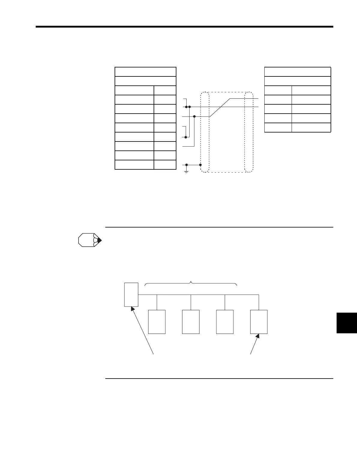
CN3 Cables
Note: 1. Connect the cable so that the terminating resistance for the 217IF is
connected.
2. Set the switch on the board to ON. For the RS-485 intermediate
stations, set the switch on the board to OFF. (VS-616G5)
1. Refer to 8.1.2 Cable Specifications for the MPE720 Programming Device connections.
2. If the terminating resistance cannot be inserted in the Module, mount 120 Ω. terminating resistance
at the end of the transmission line outside the Module. Insert the terminating resistance in the sta-
tions at both ends of the transmission path. Do not insert it in the intermediate stations.
217IF VS-616G5
MR 8-pin Screw Terminal
Signal Name Pin No. Pin No. Signal Name
RXR
41
SRD (+)
RX (-)
12
SRD (-)
RX (+)
23
SRD (+)
TXR
54
SRD (-)
TX (-)
6
TX (+)
7
SG
8
SH
3
FG
Shield
INFO
Intermediate stations
Stations (at both ends) in which the terminating
resistance is mounted