2.2 Mechanical Installation
YASKAWA ELECTRIC SIEP C710616 30B YASKAWA AC Drive T1000A Technical Manual 37
Mechanical
Installation
2
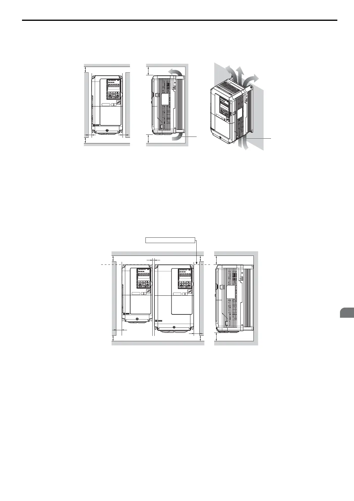
n Single Drive Installation
Figure 2.2 shows the installation distance required to maintain sufficient space for airflow and wiring.
Figure 2.2
Figure 2.2 Correct Installation Spacing
n Multiple Drive Installation (Side-by-Side Installation)
Models CIMR-T2A0004 through 0081 and 4A0002 through 0044 can take advantage of Side-by-Side installation.
When installing multiple drives into the same enclosure panel, mount the drives according to Figure 2.2.
When mounting drives with the minimum clearance of 2 mm according to Figure 2.3, derating must be considered and
parameter L8-35 must be set to 1. Refer to Temperature Derating on page 360
Figure 2.3
Figure 2.4
Figure 2.3 Space Between Drives (Side-by-Side Mounting)
Note: When installing drives of different heights in the same enclosure panel, the tops of the drives should line up. Leave space
between the top and bottom of stacked drives for easy cooling fan replacement if required.
A – 50 mm minimum C – 120 mm minimum
B – 30 mm minimum D – Airflow direction
A – 50 mm minimum C – 2 mm minimum
D – 120 mm minimum
B – 30 mm minimum
A
C
A
BB
C
D
D
Side Clearance Top/Bottom Clearance
A
A
A
A
B
C
B
D
D
Side Clearance
Line up the tops of the drives.
Top/Bottom Clearance
 Loading...


