B.3 Parameter Table
YASKAWA ELECTRIC SIEP C710616 30B YASKAWA AC Drive T1000A Technical Manual 409
Parameter List
B
n S2: Frequency Reference Gain Settings
n S3: Braking Transistor and Output Voltage Gain
n S4: KEB Mode Selection
S1-04
(683H)
Disturb Deceleration Time
Sets the deceleration time for the Disturb function.
Default: 0.0 s
Min: 0.0 s
Max: 120.0 s
251
S1-05
(684H)
Disturb Acceleration Time
Sets the acceleration time for the Disturb function.
Default: 0.0 s
Min: 0.0 s
Max: 120.0 s
251
No. (Addr.) Name Description Setting Page
S2-01
(690H)
Frequency Reference Gain
Determines how much to reduce or amplify the frequency reference. The frequency reference
cannot exceed the upper limit set to d2-01.
Default: 100.0%
Min: 0.0%
Max: 1000.0%
251
S2-02
(691H)
Frequency Reference Gain Change
Ramp
Determines the time required to accelerate from 0.0% to the gain level set in S2-01.
Default: 0.0 s
Min: 0.0 s
Max: 600.0 s
251
No. (Addr.)
<15> Values shown here are for 200 V class drives. Double the value when using a 400 V class drive.
Name Description Setting Page
S3-01
(6A0H)
Braking Transistor Operation
Selection 0: During run only
1: Always enabled
Default: 0
Min: 0
Max: 1
252
S3-02
(6A1H)
Braking Transistor Operation
Voltage Level
Sets the voltage level that triggers drive built-in the braking transistor.
Default: 394 Vdc
<15>
Min: 300 Vdc <15>
Max: 400 Vdc <15>
252
S3-03
(6A2H)
Output Voltage Gain Selection
Enables and disables the output voltage gain setting in parameter H3- = 41 (Output Voltage
Gain) or in MEMOBUS register 03H.
0: Disabled
1: Enabled
Default: 0
Min: 0
Max: 1
252
S3-04
(6A3H)
Output Voltage Gain Change Time
Sets the drive uses to change the output voltage gain set in parameter H3- = 41 (Output
Voltage Gain) or in MEMOBUS register 03H.
Default: 0.5 s
Min: 0.0 s
Max: 10.0 s
252
No. (Addr.) Name Description Setting Page
S4-01
(6B0H)
KEB Mode Selection
0: KEB disabled
1: DC bus voltage control (KEB 1)
2: Synchronous accel/decel (KEB 2)
3: Power KEB (KEB 3)
Default: 0
Min: 0
Max: 3
255
S4-02
(6B1H)
KEB Start/End Voltage
Determines how the KEB start and end voltage in parameters S4-03 and S4-06 are set.
0: Set as a Percentage of E1-01
× 1.414
1: Set as a percentage of the DC bus voltage before KEB was triggered.
Default: 0
Min: 0
Max: 1
256
S4-03
(6B2H)
KEB Start Voltage
Determines the voltage level in the DC bus that will trigger KEB. The setting value depends on
the selection in parameter S4-02. A setting of 200.0% essentially disables S4-03.
Default: 200.0%
Min: 0.0%
Max: 200.0%
256
S4-04
(6B3H)
KEB Start dV/dt Level
Sets the level of voltage fluctuation in the DC bus that triggers KEB.
Default: 0 Vdc/s
Min: 0 Vdc/s
Max: 10000 Vdc/s
256
S4-05
(6B4H)
KEB Start dV/dt filter
Sets the time required for the voltage fluctuation level defined in S4-04 to trigger KEB.
Default: 20 ms
Min: 0 ms
Max: 50 ms
256
S4-06
(6B5H)
KEB End Voltage
Sets the DC bus voltage level at that the drive assumes the power supply has returned. If this
level is exceeded for longer than S4-07 the drive starts reaccelerating to the set frequency
reference. The setting value depends on the selection in parameter S4-02.
Default: 200.0%
Min: 0.0%
Max: 200.0%
256
No. (Addr.) Name Description Setting Page
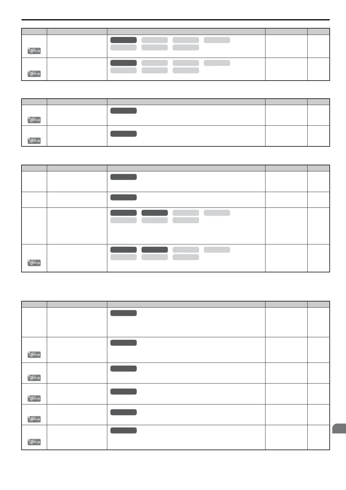
OLV/PM AOLV/PM
CLV
V/f w/PG
CLV/PM
V/f OLV
OLV/PM AOLV/PM
CLV
V/f w/PG
CLV/PM
V/f OLV
All Modes
All Modes
All Modes
All Modes
OLV/PM AOLV/PM
CLV
V/f w/PG
CLV/PM
V/f OLV
OLV/PM AOLV/PM
CLV
V/f w/PG
CLV/PM
V/f OLV
All Modes
All Modes
All Modes
All Modes
All Modes
All Modes