15.1 Inverter Drive Basics
15 -3
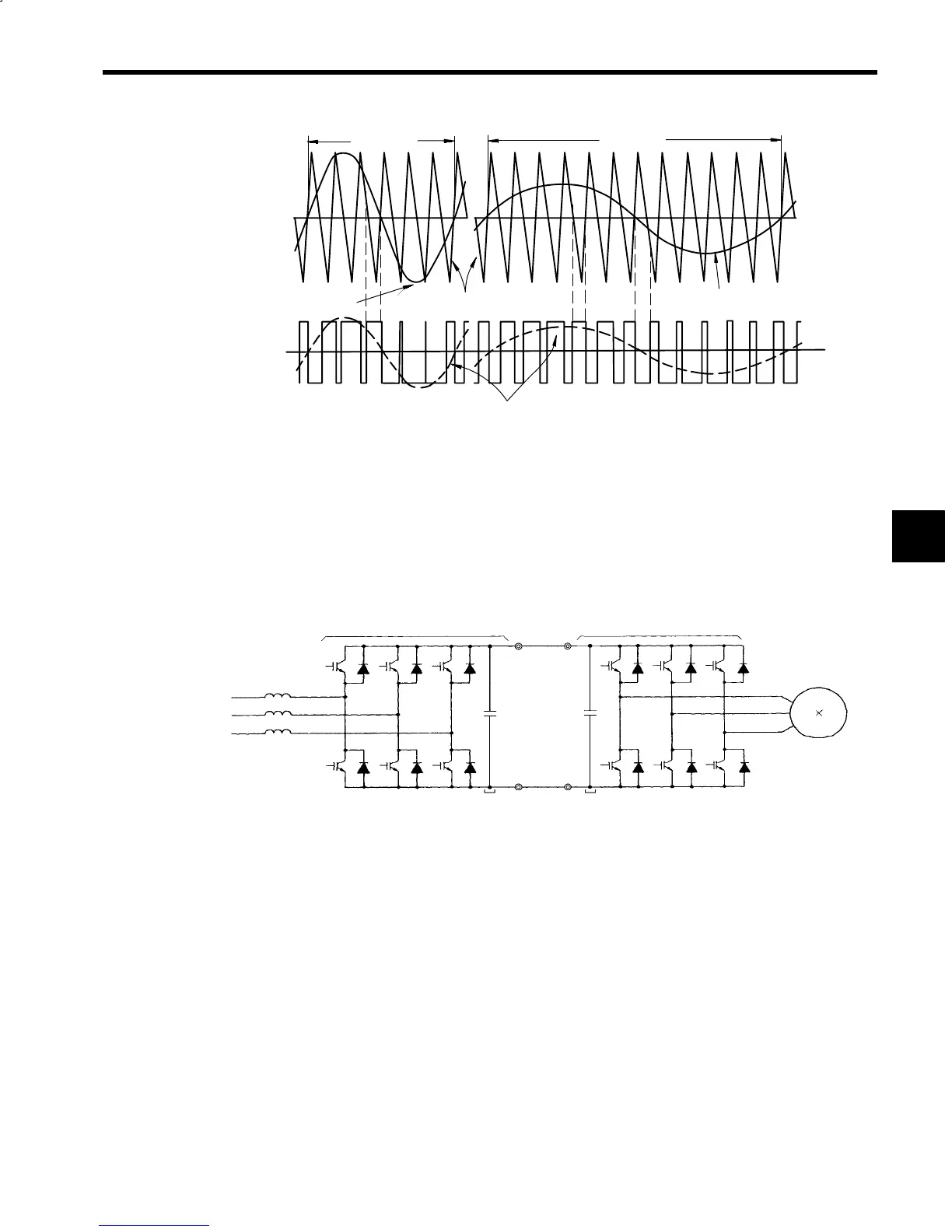
(a)
1 cycle
1 cycle
Phase−U
voltage signal
PWM carrier signal
Phase−U voltage signal
Switches
(See Fig.15.2)
Output frequenncy: High
Output voltage: High
Average output voltage
S
1,
S
3
S
4
S
2,
ON
ON
Output frequenncy: Low
Output voltage: Low
(b)
Fig 15.3 Sine Wave PWM Control
15.1.2 Inverter and Converter Configuration
As shown in Fig. 15.4, the configuration consists of a VS-656MR5 Converter, which rectifies a commer-
cial power supply and converts it to direct current, a main circuit capacitor, which smooths the rectified
voltage, and a VS-626M5 Inverter, which converts the direct current to the required AC frequency. The
converter switching element uses IGBT as used by the Inverter.
3-phase
AC power
supply
VS-656MR5 Converter
ACL
P
VS-626M5 Inverter
Induction
motor
Main circuit
capacitor
Main circuit
capacitor
N
Fig 15.4 Inverter and Converter Configuration
15.1.3 Squirrel Cage Induction Motor Characteristics
The squirrel cage induction motor characteristics are contrasted with the DC motor and the principle of
torque generation is explained below. Fig. 15.5 shows the model diagrams for each from the direction of
the axis.
Torque occurs in the DC motor using electromagnetic force proportional to the accumulated current that
flows in the armature winding, and the magnetic flux created by the magnetic field current. The torque
generated in this way is easy to control because the magnetic field windings from which the magnetic cur-
rent flows and the armature windings are independent.
On the other hand, the squirrel cage induction motor consists of a rotator with a so-called “squirrel-cage”
construction, and a stator with stator windings. When 3-phase alternating current flows through the stator
windings, a magnetic field of magnetic flux φ
m
is generated. This is equivalent to the magnetic flux gener-
ated by the DC motor magnetic field current.
Magnetic flux φ
m
can be expressed using the following formula. This current is called magnetized current
I
m
, and is almost equivalent to the unladen current of the squirrel-cage induction motor.
Formula: φ
m
= MI
m
15
 Loading...


