3.3 Wiring Main Circuit Terminals
3 -13
3.3.2 Functions of Main Circuit Terminals
The following tables outline the functions of the main circuit terminals.
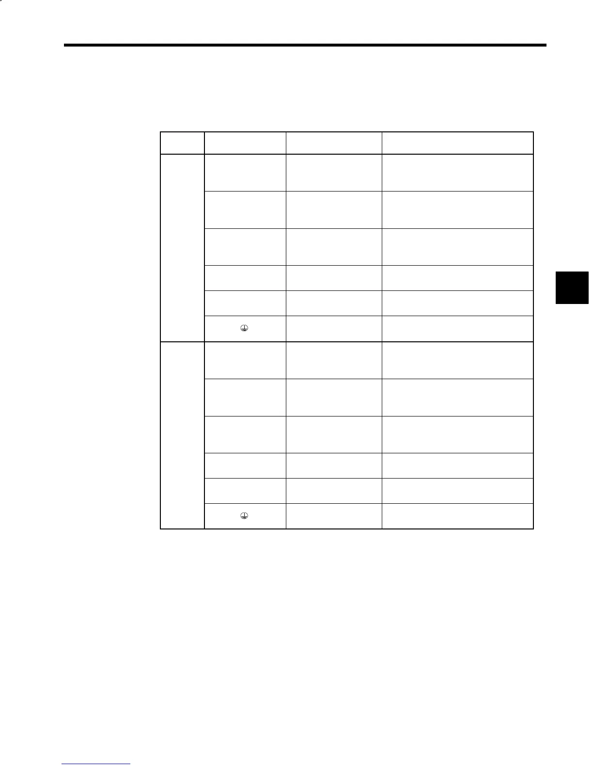
Table 3.8 Converter Main Circuit Terminals
Voltage
Class
Symbol Name Functions
R/L1
S/L2
T/L3
Main circuit power supply
input
3-phase
200 to 220 VAC 50 Hz
200 to 230 VAC 60 Hz
A1/r
A2/t
Control power supply
input
Single-phase
200 to 220 VAC 50 Hz
200 to 230 VAC 60 Hz
200 V
class
A11/r1*
A21/t1
Heatsink
Power supply input for
cooling fan
Single-phase
200 to 220 VAC 50 Hz
200 to 230 VAC 60 Hz
P/¨
N/©
Main circuit DC output
270 to 325 VDC
(For inverter main circuit power supply)
P1
N1
Control power supply
output
282 to 325 VDC
(For inverter control power supply)
Grounding
Ground terminal
(Ground resistance: 100 Ω or less)
R/L1
S/L2
T/L3
Main circuit power supply
input
3-phase
400 to 440 VAC 50 Hz
400 to 460 VAC 60 Hz
A1/r
A2/t
Control power supply
input
Single-phase
200 to 220 VAC 50 Hz
200 to 230 VAC 60 Hz
400 V
class
A11/r1*
A21/t1
Heatsink
Power supply input for
cooling fan
Single-phase
200 to 220 VAC 50 Hz
200 to 230 VAC 60 Hz
P/¨
N/©
Main circuit DC output
540 to 650VDC
(For inverter main circuit power supply)
P1
N1
Control power supply
output
282 to 325VDC
(For inverter control power supply)
Grounding
Ground terminal
(Ground resistance: 10 Ω or less)
* Terminals on Open Chassis Converters with a minimum capacity of 11 kW.
3