12.2 Converter Faults
12 - 3
12.2 Converter Faults
If a fault occurs during operation, protective functions are activated depending on the fault and operation is
stopped. The contents of the faults are displayed numerically on the 7-segment display.
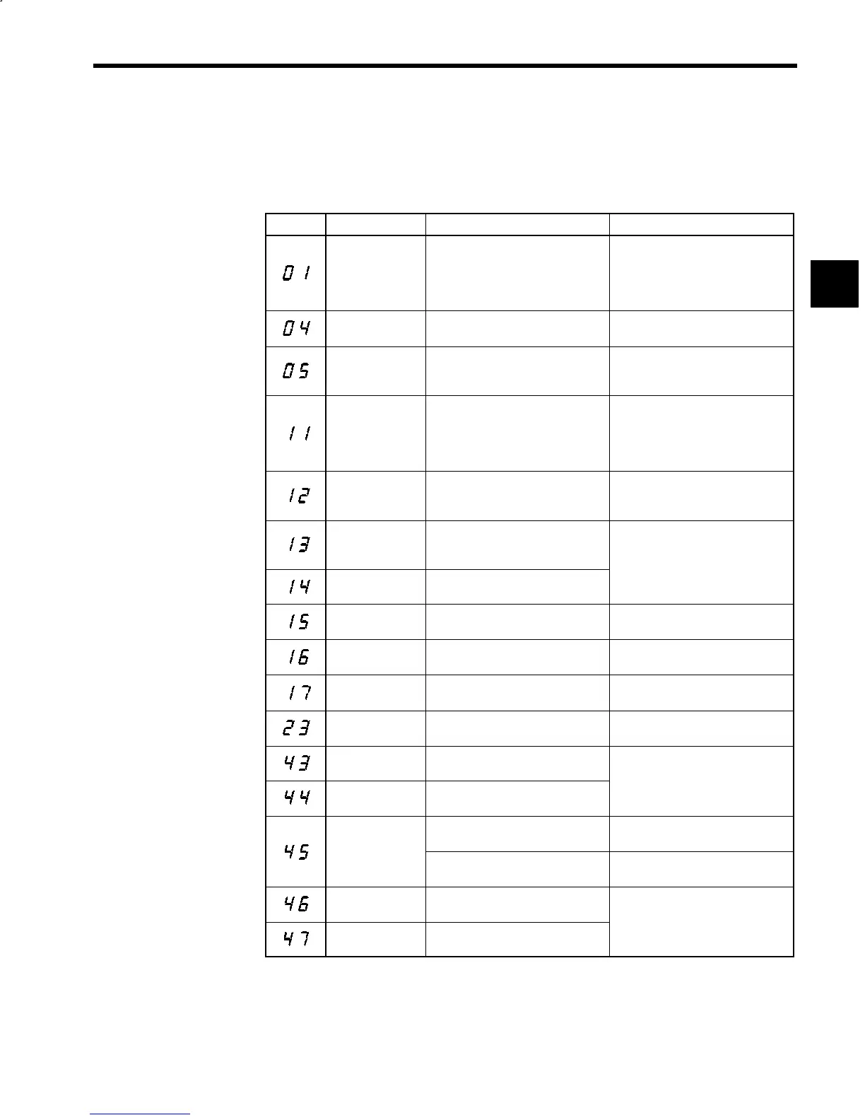
Table 12.1 Converter Faults
Fault No. Name Meaning Corrective Actions
Overcurrent
Output current exceeded overcurrent
detection level.
S Check the wiring.
S Check the input supply voltage.
S Check the AC reactor.
S Check the load shaft (Inverter, Servo)
capacity.
Main circuit fuse
blown
Main circuit fuse was blown.
Check for damaged transistor, load
short circuit, ground short, etc.
Overload
Output current exceeded overload lev-
el.
S Reduce the load.
S Check the load shaft (Inverter, Servo)
capacity.
Output overvoltage
Output voltage exceeded overvoltage
level.
Detection level:
200 V class: Approx. 400 V
400 V class: Approx. 800 V
S Check the input supply voltage.
S Check the load shaft
(Inverter, Servo) capacity.
Main circuit under-
voltage
Main circuit output voltage became
lower than undervoltage detection lev-
el.
Check the input supply voltage.
Control circuit un-
dervoltage
Control circuit power supply became
lower than undervoltage detection lev-
el.
Check the control su
ly voltage.
Servo unit power
supply fault
Control supply voltage supplied to Ser-
vo Unit was not normal.
.
Power supply fre-
quency fault
Excessive power supply frequency
deviation (50 Hz or 60 Hz ±5%)
Check the input power waveform.
Initial charging
fault
Charging of main circuit capacitor was
not completed within set time.
Replace the Unit.
Power supply open
phase
An open phase occurred at input sup-
ply.
S Check the input supply voltage.
S Check the wiring.
Built-in MC opera-
tion fault
Magnetic contactor did not function. Replace the Unit.
Heatsink overheat
1
Heatsink temperature exceeded upper
limit (minor fault).
Check the ambient tem
erature for ef-
Heatsink overheat
2
Heatsink temperature over upper limit
continued for one minute or longer.
fective cooling.
Heatsink thermis-
Thermistor for heatsink temperature
detection was disconnected.
Replace the unit.
tor disconnection
The ambient temperature is low
(−20°C(−4°F) or below).
Raise the ambient temperature to above
−20°C(−4°F).
Control PCB tem-
perature fault 1
Control PCB temperature exceeded
80°C (176°F) (minor fault).
Check the ambient tem
erature for ef-
Control PCB tem-
perature fault 2
Control PCB temperature exceeded
85°C (185°F).
fective cooling.
12
 Loading...


