Magnetic Sensor Orientation Control
9.5.1 Magnetic Sensor Signal
9-8
9.5 Connections between Devices
This section explains the connections between the devices used for Magnetic Sensor orientation control.
9.5.1 Magnetic Sensor Signal
J
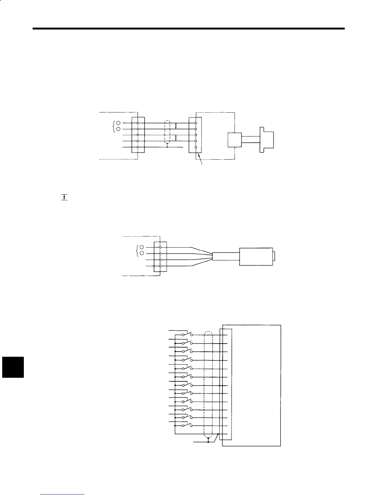
Using the FS-1378C
Orientation card
Position signal
(See note 1.)
(See note 2.)
FSD-1378C
Magnetic
Sensor
Amplifier
FSH-1378C
Sensor
Head
Metal connector
(supplied)
+
+15 V
SG
SG
13
10CN
14
12
3
1
P
P
A
D
C
B
−
Notes:1. Use a model 2P 0.3-mm
2
twisted-paired vinyl cable with copper shielding. Make sure the wiring distance is 20 m maxi-
mum.
2.
P
indicates twisted-pair cable.
Fig 9.8 Connection between Devices for FS-1378C
J
Using the FS-200A
Orientation Card
Position signal
Green
White
Red
Black
+
−
+12V
SG
13
10CN
14
10
3
FS-200A
Magnetic
Sensor
Fig 9.9 Connection between Devices for FS-200A
9.5.2 Stop Position References
Stop position references stop the motor at a user-set position using Magnetic Sensor orientation.
Binary
Controller
1CN
D1 (P01)
D2 (P02)
D3 (P03)
D4 (P04)
D5 (P05)
D6 (P06)
D7 (P07)
D8 (P08)
D9 (P09)
D10 (P10)
D11 (P11)
D12 (P12)
COM
1
2
4
8
16
32
31
64
128
256
512
1024
2048
30
29
28
27
26
25
24
23
22
21
20
19
Note: For the connector terminal arrangement, refer to 3.4 Wiring Control Circuit Signals.
Fig 9.10 Connection between Devices
9
 Loading...


