Magnetic Sensor Orientation Control
9-2
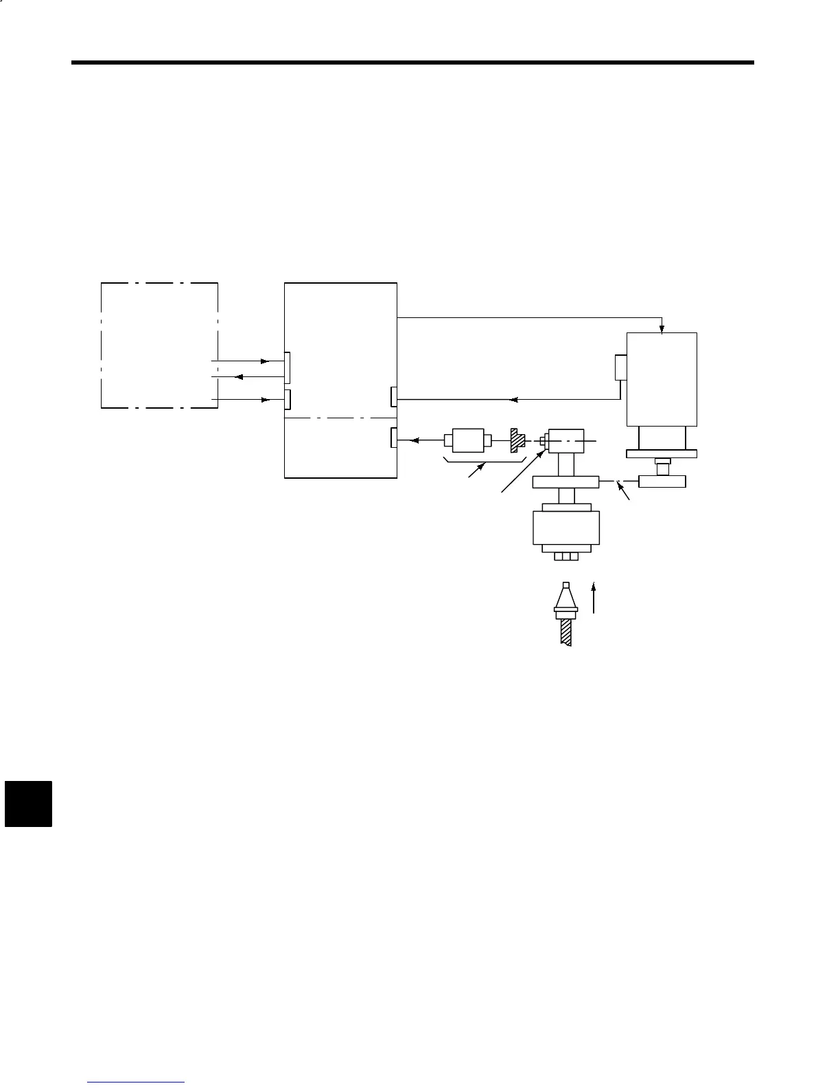
9.1 Device Configuration
This configuration performs positioning to a fixed angle by detecting the position using a Magnetic Sensor
mounted on a fixed part and a Magnet mounted to the rotating part of the load shaft. For this method of control,
the following devices are required in addition to signals and speed references for forward and reverse rotation:
Orientation signals and a Magnet for positioning references, a Magnetic Sensor, and a Magnetic Sensor
Orientation Card.
In addition, after performing positioning using the Magnetic Sensor, user-set position stop control can be per-
formed using an incremental operation. For this operation, stop position references are required.
NC panel
Orientation signal
gear selection
Orientation
Stop position
reference
Magnetic Sensor
orientation card
Motor encoder
signal
Magnetic Sensor
Magnet
Main shaft
Tool
AC main
shaft motor
Transmission mechanism
(gears, belt, etc.)
VS−626M5
6CN
1CN
2CN
10CN
Fig 9.1 Main Shaft Orientation Device Configuration for Magnetic Sensor Method
9