6.4 Constant Settings
6-9
6.4 Constant Settings
This section explains the user constant functions and settings.
6.4.1 User Constant Functions Table
A table of user constant functions is shown below. Change the constant set values depending on the operat-
ing specifications. Refer to 5.3.4 Control Constant Display Mode for setting methods.
Check that the following constant set values match the operating specifications.
D
Inverter settings
D
Machine specification settings
D
Sequence input signal settings
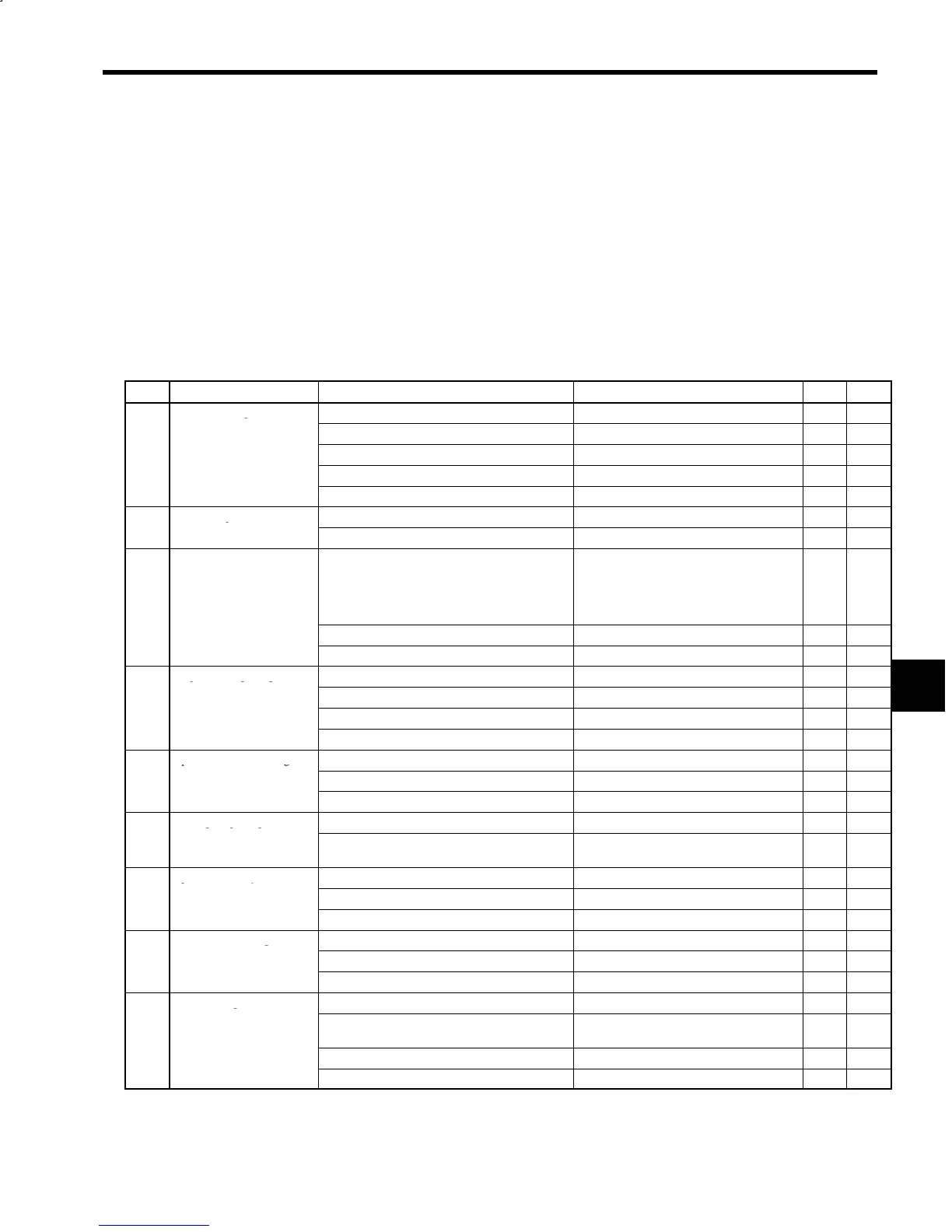
Table 6.3 User Constant Functions
No. Item Details Related Constants M5A M5N
1
Inverter settings
Inverter Capacity Selection C1-56 ON ON
Motor Code Selection C1-25 ON ON
Orientation Control Method Selection C1-39 bit 0 ON ON
YENET1200 Card Encoder Selection C1-58 bit 0 OFF ON
RUN Mode Selection C1-37 bits 1 and 0 ON ON
2
Machine specification
Rated Speed C1-26 ON ON
settings
Gear Ratio Settings C1-27 to 29 ON ON
3
Sequence input signal
settings
Sequence Input Signal Selections C1-36 bits 1 and 0 (TLL/INC)
C1-36 bit 3 (SSC/SV)
C1-36 bit 4 (PPI/LM10)
C1-37 bit 2 (RDY/EMG2)
C1-40 bit 3 (ORT/NCORT)
ON ON
Torque Limit Signal C1-24 and C1-38, bit 2 ON ON
12-bit Digital Reference Signal Selection C1-36 bit 7 (Speed/position reference) ON OFF
4
Sequence output signal
Zero-speed Detection Level (ZSPD) C1-19 ON ON
settings
Speed-agree Signal (AGR) C1-20 and C1-38 bit 6 ON ON
Speed Detection Signal (SDET) C1-21 and C1-22 ON ON
Torque Detection Signal (TDET) C1-23 and C1-40 bit 2 ON ON
5
Speed reference settings
Soft Start Time Setting C1-10 ON ON
Analog Speed Reference Adjustments C1-11, C1-12, and C1-38 bit 5 ON OFF
Digital Speed Reference Settings C1-37 bits 7 and 6, and C1-41 to 48 ON OFF
6
Analog output signal
Speedometer Signal Adjustments C1-16 and C1-54 ON OFF
settings
Load Factor Meter Signal Adjustments C1-17, C1-55, C1-18, C1-38 bits 1 and 0,
C1-38 bit 7, and C1-40 bit 4
ON OFF
7
Speed control system
Speed Control Gain Adjustments C1-01 to 04 ON ON
adjustments
Motor Flux Lower Limit Level C1-30 ON ON
Torque Reference Filter Time Constant C1-09 ON ON
8
Servo mode settings
Analog Speed Reference Gain in Servo Mode C1-38 bit 3, C1-40 bit 5, C1-49, and C1-50 ON OFF
Servo Mode Flux and Base Speed Ratio C1-31 to 34 ON ON
Speed System Adjustment in Servo Mode C1-05 to 08 ON ON
9
Other settings
Zero-speed Braking Time C1-35 ON ON
Excessive Speed Deviation Protection Operation
Adjustments
C1-38 bit 4, and C1-40 bits 1 and 0 ON ON
Load Fault Detection Selection C1-40 bit 7 ON ON
Fault Record Clear Selection C1-57 bit 0 ON ON
M5A: Stand-alone drive (analog speed reference settings); M5N: NC system (YENET1200 serial communica-
tions)
ON: Constant valid; OFF: Constant not valid (Not used.)
6
 Loading...


