15.2 Basic Inverter Drive mechanics
15 -7
15.2.3 Inertial Moment and GD
2
Inertial moment is a measure of the ease of the rotation operation of the rotator. Taking the total mass m
(kg) of the rotator, and the rotation radius r (m), the inertial moment J can be expressed using the following
formula.
J = mr
2
(kg
⋅
m
2
)
The relationship to the flywheel effect GD
2
that has been used until now can be expressed using the follow-
ing formula.
J =
GD
2
4
(kg
⋅
m
2
)
The various inertial moment shapes are summarized below. Friction and other losses, however, have not
been considered, and the efficiency is taken to be 1.
J
Cylindrical Inertial Moment
Inertial moment J
1
during rotation along an axis centered on the mass m
1
(kg) and radius r
1
(m) of a cylinder
can be expressed using the following formula.
J
1
=
m
1
r
1
2
2
(kg
⋅
m
2
)
r
1
(m)
L (m)
Mass m
1
(kg)
Fig 15.10 Cylindrical Inertial Moment
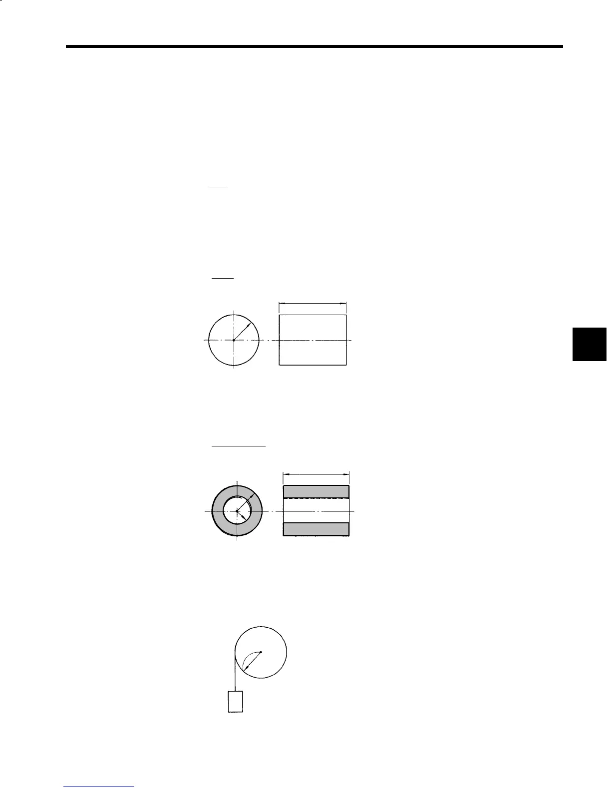
J
Tubular Inertial Moment
Inertial moment J
2
during rotation along an axis centered on the mass m
2
(kg), outer radius r
1
(m), and inner
radius r
2
(m) of a cylinder can be expressed using the following formula.
J
2
=
m
2
(r
1
2
+ r
2
2
)
2
(kg
⋅
m
2
)
r
1
(m)
r
2
(m)
L (m)
Mass m
2
(kg)
Fig 15.11 Tubular Inertial Moment
J
Load Reel Inertial Moment
Inertial moment J
3
of a load reel, as shown in Fig. 15.12, concentrates the entire load on the contact point
between a rope and pulley, and can be expressed using the following formula.
J
3
= m
3
r
1
2
(kg
⋅
m
2
)
Rope
Pulley
r
1
(m)
m
3
(kg)
Fig 15.12 Load Reel Inertial Moment
15
 Loading...


