8.5 Load Shaft Encoder Connector Terminal Arrangement
8-7
8.5 Load Shaft Encoder Connector Terminal Arrangement
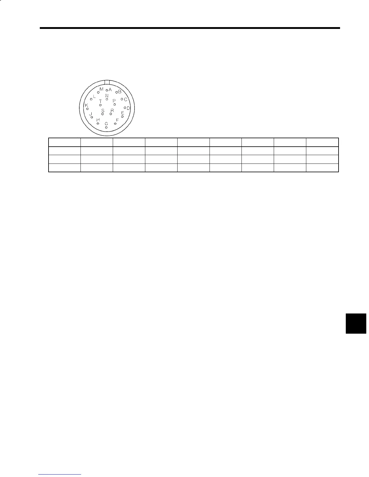
The connector terminal arrangement for the Load Shaft Encoder is shown in the following diagram.
Encoder: MS3102A20-29P
Cables: MS3106A20-29S (Straight plug, solid shell)
MS3106B20-29S (Straight plug, 2-piece shell)
MS-3108B20-29S (L−plug, 2-piece)
MS3057-12A (Cable Clamp)
A
B C D E F G H I
PA PC PB --- FG --- --- 5V ---
K L M N P R S T ---
0V --- --- *PA *PC *PB --- --- ---
Notes: 1. The asterisk (*) for signals *PA, *PB, and *PC indicates reverse rotation signals.
2. The connectors are manufactured by Nihon Koku Denshi Kogyo (KK).
Fig 8.7 Load Shaft Encoder Connector Terminal Arrangement
8
 Loading...


