Operating the Digital Operator
5.3.1 Indication at Power-ON
5-6
5.3 Key Operations and Display
This paragraph describes how to operate the Digital Operator keys and display.
5.3.1 Indication at Power-ON
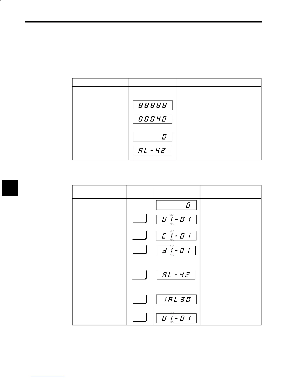
Digital Operator display at control power supply ON is shown below.
Description Digital Operator Display Remarks
S Turn ON control power sup-
ply.
S All LEDs light.
Displayed for 1.5 sec.
S PROM number is displayed.
Displayed for 0.5 sec.
The lower 5 digits of PROM No. are displayed.
The example uses PROM No. “VSM200040.”
S U1-01 (motor speed) data is
displayed.
Because the motor does not rotate when power
supply is turned ON, “0” is displayed.
S The fault No. is displayed.
(Displayed when a protective
function is activated.)
(
)
AL-42 indicates motor thermistor is disconnected
when motor encoder signal 2CN is disconnected.
5.3.2 Switching Display Functions
Depress [DSPL] key on the Digital Operator to change the mode of display.
Description
Key
Sequence
Digital Operator Display Remarks
S Motor speed (U1-01) data is
displayed.
S Motor speed data No. is dis-
played. (Operation status
display has been selected.)
DSPL
Control signal status of each unit can
be monitored.
S Control constants display is
selected.
DSPL
Control constants are displayed/set.
S Digital Operator run com-
mand display is selected.
(Displayed when bits 0 and
1 of control constant C1-37
are set ON.)
DSPL
(
)
Use when operating by Digital Oper-
ator.
S The fault No. display is se-
lected. (Displayed when a
protective function is acti-
vated.)
DSPL
(
)
Contents of currently occurring
fault are displayed.
AL-42 indicates motor thermistor
disconnection is detected.
S Fault record display is se-
lected.
DSPL
Contents of past faults are displayed.
1AL30 indicates the last fault is en-
coder signal disconnection.
S Returns to operation status
display.
DSPL
5
 Loading...


