3.3 Wiring Main Circuit Terminals
3 -15
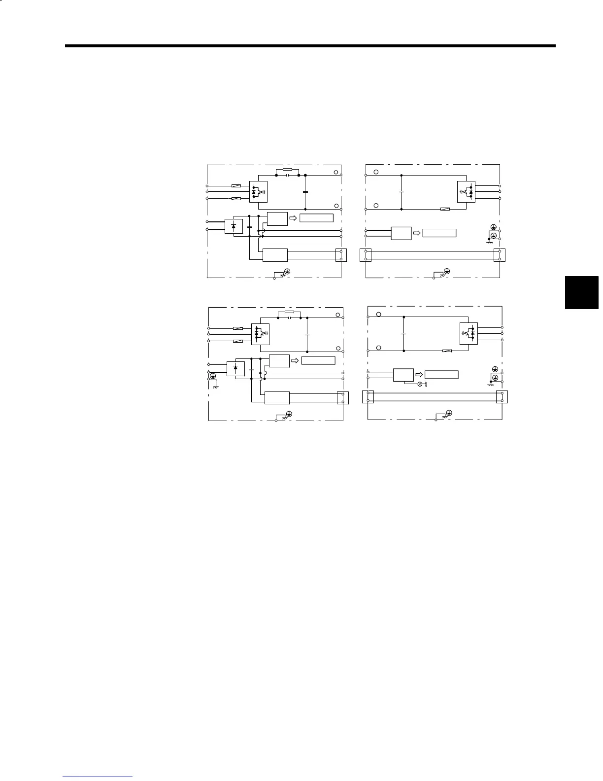
3.3.3 Main Circuit Configuration
The following diagrams show the main circuit configurations.
J 200 V Class External Heatsink Cooling Type
CIMR−MR5j23P75 to 27P55 CIMR−M5j23P75 to 27P55
+24 V
Power
Supply
(RCC)
Control Circuit
Power
Supply
Converter (VS-656MR5)
Inverter (VS-626M5)
+
+
P/
−
N/
R/L1
S/L2
T/L3
A1/r
A2/t
P1
N1
5CN
+24V
0V
+
P/
N/
U/T1
V/T2
W/T3
P1
N1
51CN
52CN
0V
+
(Note)
Control Circuit
Power
Supply
(RCC)
+24V
(Note)
+
−
+
+
P/
−
N/
R/L1
S/L2
T/L3
A1/r
A2/t
P1
N1
5CN
+24V
0V
+
P/
N/
U/T1
V/T2
W/T3
P1
N1
51CN
52CN
+24V
0V
+
Converter (VS-656MR5) Inverter (VS-626M5)
CIMR-MR5j20115 to 20375 CIMR-M5j20115 to 20375
+24 V
Power
Supply
(RCC)
Control Circuit
Power
Supply
Control Circuit
Power
Supply
(RCC)
(Note)
Internal Cooling Fan
+
−
Note: The +24-V power supply is provided to models for NC systems.
Fig 3.5 Main Circuit Configurations of 200 V Class Inverters with External Heatsink Cool-
ing
3