Wiring
3.3.2 Functions of Main Circuit Terminals
3 -14
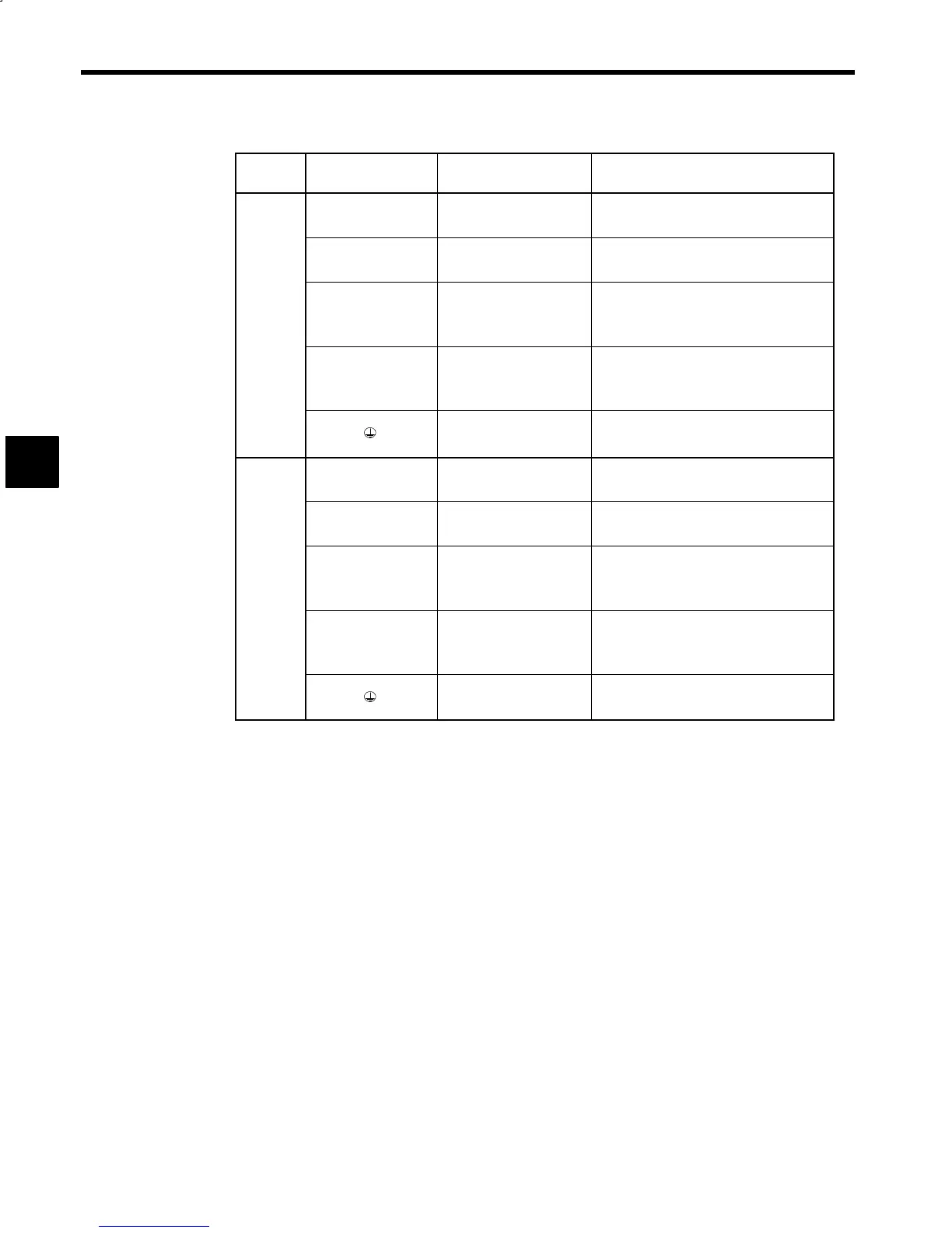
Table 3.9 Inverter Main Circuit Terminals
Voltage
Class
Symbol Name Functions
P/¨
N/©
Main circuit power supply
input
270 to 325 VDC
(Supplied from converter)
P1
N1
Control power supply
input
282 to 325 VDC
(Supplied from converter)
200 V
class
A12/r2*
A22/t2
Heatsink
Power supply input for
cooling fan
Single-phase
200 to 220 VAC 50 Hz
200 to 230 VAC 60 Hz
U/T1
V/T2
W/T3
Inverter output Inverter output to motor
Grounding
Ground terminal
(Ground resistance: 100 Ω or less)
P/¨
N/©
Main circuit power supply
input
540 to 650 VDC
(Supplied from converter)
P1
N1
Control power supply
input
282 to 325 VDC
(Supplied from converter)
400 V
class
A12/r2*
A22/t2
Heatsink
Power supply input for
cooling fan
Single-phase
200 to 220 VAC 50 Hz
200 to 230 VAC 60 Hz
U/T1
V/T2
W/T3
Inverter output Inverter output to motor
Grounding
Ground terminal
(Ground resistance: 10 Ω or less)
* Terminals on Open Chassis Inverters with a minimum capacity of 11 kW.
3
 Loading...


