Wiring
3.4.4 Sequence Input Signal Circuit (for Stand-alone Drive)
3 -32
3.4.4 Sequence Input Signal Circuit (for Stand-alone Drive)
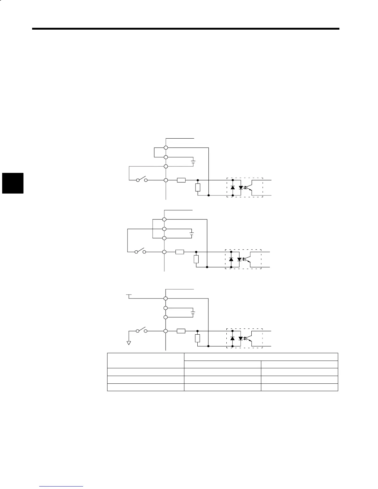
Design the input signals in consideration of the following conditions.
D
The 12-bit digital reference signals into the Inverter’s 1CN connectors and the sequence input signals
into 6CN connectors can be 0 V, 24 V, or external common signals. The wiring of terminals varies with
the input method as shown below.
D
To select the external common method, prepare a 24-V (20 to 26 V) power supply for the input signal.
D
The 1CN common and 6CN common terminals are insulated. Therefore, it is possible to used the com-
mon terminals individually.
D
If a relay contact is used, the minimum contact capacity must be 5 mA at 30 V.
D
There will be a signal delay of approximately 5 ms due to the input filter.
0 V Common
+24 V Common
External Common
+24 V (or 0 V)
0 V (or +24 V)
EXTCOM
24VCOM
0VCOM
3.3kΩ
390Ω
EXTCOM
24VCOM
0VCOM
3.3kΩ
390Ω
EXTCOM
24VCOM
0VCOM
3.3kΩ
390Ω
Pin Number
gna
ame
1CN 6CN
EXTCOM 31 19, 20, 21
24VCOM 32 22, 23
0VCOM 33 24, 25
Fig 3.20 Input Method Selections
3